2 Setting up a system
MX Modules A04089_07_E00_02 HBM: public 21
Instructions (typical use case)
Assemble a stack before applying serviceable (blue) threadlock to Phillips head
screws.
1. Apply serviceable (blue) threadlock to the four (4) M5 set screws (E) in each
caselink (D). Use a 2.5 mm hex wrench to turn set screws back in the
caselinks before installing the caselinks on a module.
2. Insert two caselinks (D) in the slots on each end of the SomatXR module.
3. Tighten the set screws (E) in each caselink on the module, using a 2.5 mm hex
wrench. Tighten the screws to 3.6 N-m (32 in-lbs) torque.
4. Align the bracket (J) with the caselinks on the module.
5. Connect a bracket (J) to the caselinks using M5 flat screws (A), serviceable
(blue) threadlock and a #2 Phillips screw driver. Apply serviceable threadlock
and tighten each screw until secure using a #2 Phillips screw driver.
Optional equipment installation on the universal mounting bracket
Only one MOXA AWK-4121, 1-EGPS200-B-2, 1-EGPS200-P-2 or Sierra Wireless
PinPoint X or XT unit will fit on the universal mounting bracket.
The following equipment may be installed on the universal mounting bracket:
1.
Sierra Wireless AirLink GX450 and 1-EGPS-5HZ-2 or Axis camera
2.
ACKSYS WLg-xROAD/N or /NP and 1-UPX002-2 or 1-EGPS-5HZ-2 or Axis
camera
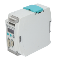
3. Two (2) 1-UPX002-2 units
4.
1-UPX002-2 and ACKSYS WLg-xROAD/N or /NP or 1-EGPS-5HZ-2 or Axis
camera
5.
Axis camera and L-Com BT-CAT6P1HP-48W
6.
L-Com BT-CAT6P1HP-48W and PoE Power injector power supply (Axis
camera mounted separately)
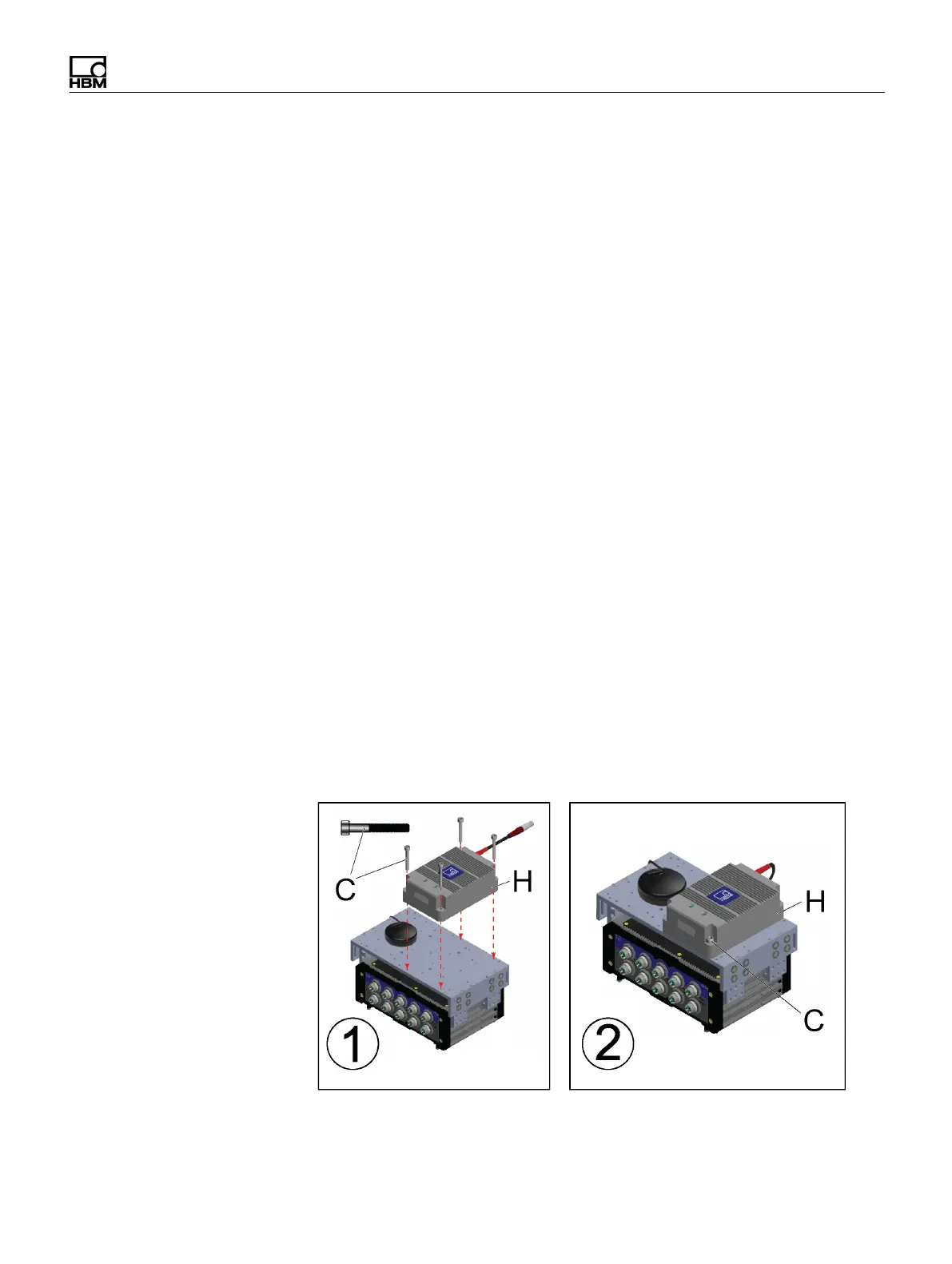
Example of Accessory Mounting: Installing a UPX series Uninterruptible
Power Supply