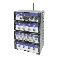
4 Modules
54 A04089_07_E00_02 HBM: public MX Modules
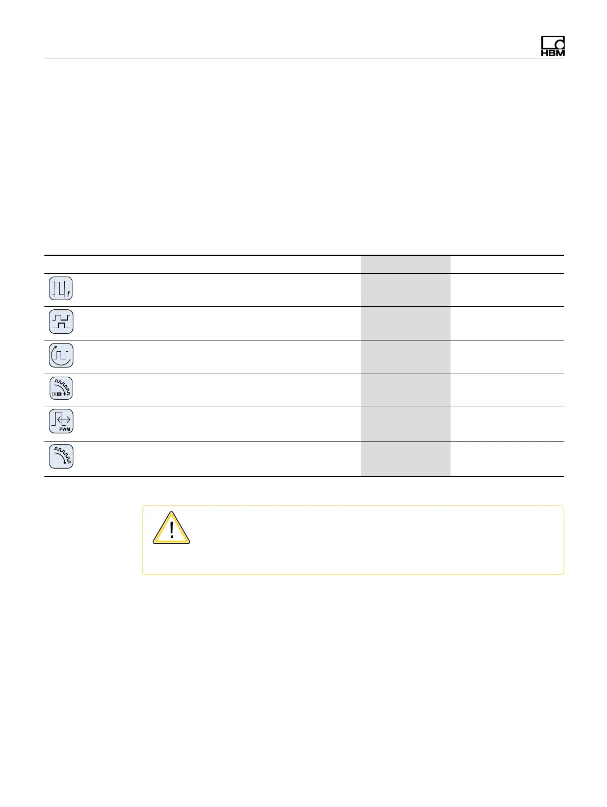
4.7 MX460B-R frequency / counter module
Up to four (4) digital inputs may be connected to the MX460B-R, to measure digital
pulses up to 1 MHz (speed, torque, angle position, displacement, PWM in general).
CX23-R/EXRCPU/EXRLCPU support is limited in the following aspects. Math
functions are not supported. Interactive zeroing of the “crank shaft” sensors is not
supported.
You can connect up to four transducers to the frequency measuring amplifier
MX460B-R. Transducers are connected via a 14‐pin ODU device socket. All
measuring channels are electrically isolated from one another and from the mains.
When using the adjustable sensor supply, electrical isolation from the supply voltage
of the amplifier is rescinded.
Transducer MX460B-R Wiring diagram
Frequency / pulse counter
(timer, TTL)
● 82
Incremental encoder
(timer, TTL)
● 82
Torque / speed
● 82
Passive inductive encoder
● 90
PWM - Pulse width, pulse duration, period duration
● 91
Crank wheel sensor
● 96
CAUTION
The MX460B can supply sensors with a constant DC voltage of 5 to 24 volts.
Always check encoder data sheet for maximum supply voltage. Supplying a
sensor supply of 12 volts to a 5-volt encoder may damage it.
When TEDS or T-ID is used, the measurement channel is automatically
parameterized after connection.