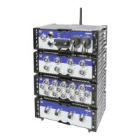
2 Setting up a system
32 A04089_07_E00_02 HBM: public MX Modules
If an external synchronization source is set, the module with the best
synchronization quality automatically becomes the master and synchronizes all
modules connected via FireWire.
Other synchronization methods
n EtherCAT®: To time-synchronize via EtherCAT®, a SomatXR CX27C-R or
QuantumX CX27C Industrial Ethernet Gateway is required. For details, please
refer to the CX27 manuals.
n IRIG-B: IRIG-B is a standardized time coding and can only be used in
combination with a MX840B(-R) module.
To time-synchronize the SomatXR system, the digital or analog modulated time
signal is sent externally to any analog voltage input of the MX840B(-R).
The B127 format uses analog modulation. Connection is identical to that of a "10 V
voltage" input.
The other formats are BCD-coded and must be connected analogous to the input
"Frequency, single-pole, without directional signal".
The amplifiers can record IRIG-B signals of type B000 to B007 and B120 to B127. All
modules connected via FireWire are also automatically synchronized. The coding
includes the time, year and optionally, the seconds of the day.
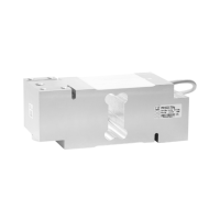
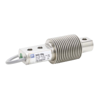
2.7 Connecting transducers
Shielding design
Sources of interference can cause electromagnetic fields which can induce
interference voltages inductively or capacitively via the connection cable and device
housing in the measurement circuit and therefore interfere with the device function. It
must be ensured that the devices used in the system also do not transmit any
electromagnetic interferences. Electromagnetic compatibility (EMC), which
encompasses both the required electromagnetic interference immunity (EMI) and the
permissible electromagnetic interference emissions (EME), has become
increasingly important over the years.
According to the HBM Greenline shielding concept, the measuring chain is
completely enclosed by a Faraday cage by appropriate routing of the cable shield.
The cable shield is extensively connected with the transducer housing and is routed
via the conductive plug to the amplifier housing. The influence of electromagnetic
interferences is significantly reduced by these measures.
NOTE
All parts of the measurement chain (including all cable connection points such as
plugs and couplings) must be surrounded by a closed EMC‐proof shield. Shield
junctions must represent a full contact, closed and low‐impedance connection.
This is the case for original HBM plug connections.
Ground connection and grounding
As the signal ground and shielding are separated in EMC‐compliant cabling, the
shielding can be connected at more than one point to the ground, i.e. via the