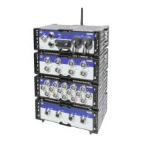
4 Modules
MX Modules A04089_07_E00_02 HBM: public 51
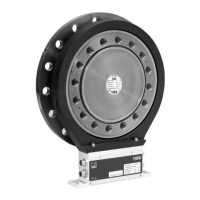
4.6 MX411B-R highly dynamic universal module
Up to four (4) electrically isolated inputs can be connected to the MX411B-R module,
including strain gage and inductive bridges, standardized voltage and DC current
sources (20 mA) or current-fed piezoelectric (IEPE, ICP®) and piezoresistive
transducers.
Transducer MX411B-R Wiring diagram
Strain gage, full bridge
six-wire configuration
● 64
Strain gage, half bridge
five-wire configuration
● 64
Strain gage, quarter bridge
three- or four-wire configuration
●
*
3-wire only
64
Inductive full bridge
● 68
Inductive half bridge
● 68
Piezoresistive transducer
● 71
Voltage,
10 V
●
10 V only
74
Current-fed piezoelectric transducer
(IEPE, ICP®)
●
†
75
Current, 20 mA
● 76
*
Use quarter bridge adapter 1-SCM-R-SG1000-2, 1-SCM-R-SG120-2 or 1-SCM-R-SG350-2.
†
Use ODU 14-pin to BNC adapter 1-KAB430-0.3.
The measurement channels are electrically isolated from each other and from the
power supply. When using the adjustable transducer excitation, electrical isolation
from the supply voltage is not required.