1 Introduction
MX Modules A04089_07_E00_02 HBM: public 13
1.3 About the documentation
The SomatXR documentation consists of:
n Printed quick start guides for initial startup.
n User manuals for the SomatXR series in PDF format.
n Various data sheets for SomatXR modules and accessories.
n Several PDF mounting instructions for cables, adapters and connectors.
n Comprehensive online help and easy search options are available after the
installation of the Windows PC software (for example, MX Assistant and
catman®EASY).
These documents can be found:
n On the SomatXR system DVD supplied with the modules.
n After installation of the MX Assistant software on your local PC.
n Up-to-date versions are always available at www.hbm.com/somatxr.
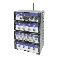
1.4 MX modules
All SomatXR MX modules can be combined with MX modules of the QuantumX
(MX...) series and can be connected to the CX22 data recorder and Ethernet
gateway and the CX27 Ethernet and Industrial Ethernet Gateway. There are some
limitations when using the SomatXR data recorder CX23-R and the Somat eDAQXR
and eDAQXR-lite CPU layers (see the corresponding manual).
The connection interfaces on the rear are identical to Ethernet and FireWire. The MX
modules of the SomatXR series offer additional functions. In principle, they can be
synchronized using the FireWire or Ethernet-based PTPv2 protocol (IEEE1588).
Furthermore, decimal data rates are available in addition to the "Classic HBM Data
Rates".
Each MX module has a similar back panel with a power connector, two FireWire
connectors, and one Ethernet connector.
MX module features
All MX modules have the following in common:
n Low voltage connection
n Configurable Ethernet interface for data communication with an operating PC
n Two FireWire interfaces
o
For optional voltage supply (note data sheet)
o
For optional data communication with a PC
o
For synchronization of the modules
o
For internal measured data transmission
n Status LEDs to display current module status
n A factory calibration certificate is stored on each amplifier, which can be read out