1 Introduction
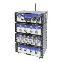
12 A04089_07_E00_02 HBM: public MX Modules
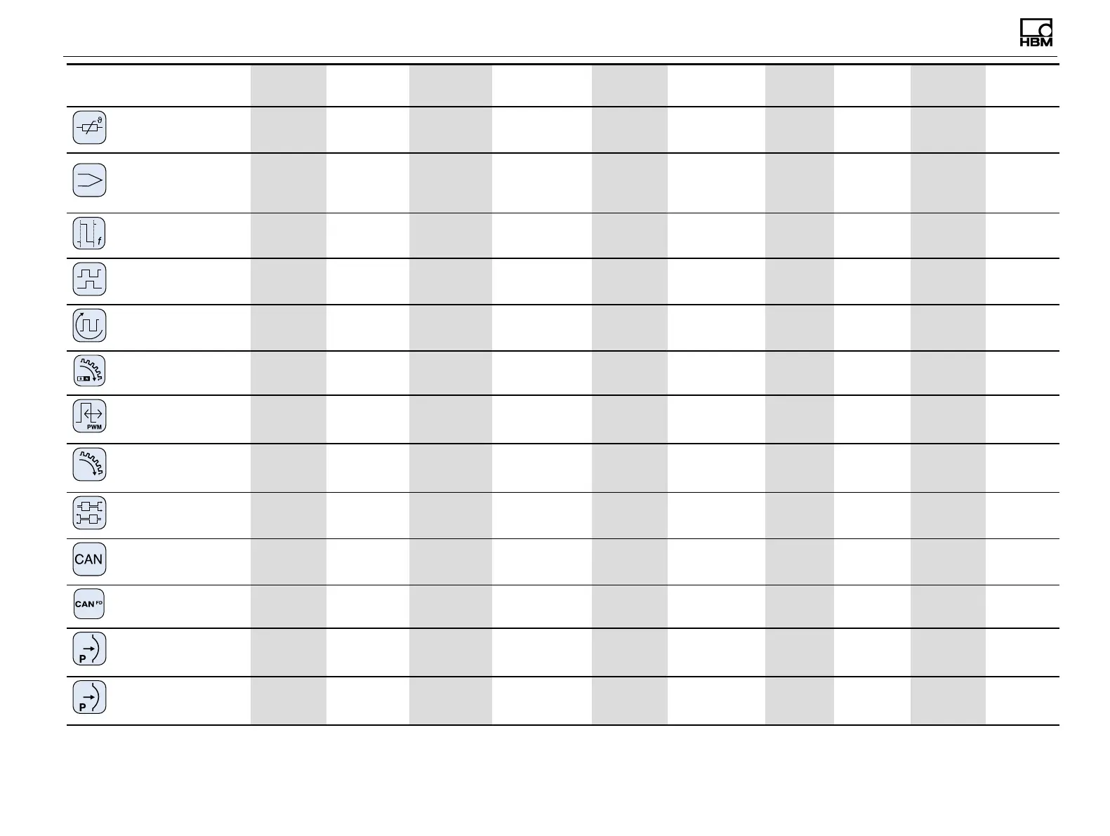
Transducer MX840B-R MX1615B-R MX1601B-R
MX1609KB-R
MX1609TB-R
MX411B-R MX460B-R MX471B-R MX471C-R MX590B-R
Wiring
diagram
Resistance thermometer
(RTD), PT100 or PT1000
●
●
PT100 only
78
Thermocouple
●
‡
●
K-type or T-type
respectively
80
Frequency / pulse counter
(timer, TTL)
●
connectors 5-8
●
82
Incremental encoder
(timer, TTL)
●
connectors 5-8
●
82
Torque / speed
●
connectors 5-8
●
82
Passive inductive encoder
●
90
PWM - Pulse width, pulse
duration, period duration
●
91
Crank wheel sensor
●
96
SSIprotocol
●
connectors 5-8
82
CAN bus
●
connector 1
●
§
●
§
93
CAN FD bus
●
93
Absolute pressure
(gas/fluid) sensor
●
95
Relative pressure
(gas/fluid) sensor
●
95
*
Use quarter bridge adapter 1-SCM-R-SG1000-2, 1-SCM-R-SG120-2 or 1-SCM-R-SG350-2.
†
Optional: ODU 14-pin to BNC adapter 1-KAB430-0.3.
‡
Use thermocouple adapter 1-SCM-R-TCK-2 for K-
type, 1-SCM-R-TCE-2 for E-type, 1-SCM-R-TCT-2 for T-type and 1-SCM-R-TCJ-2 for J-type.
§
Including support for CCP/XCP-on-CAN (not in combination with CX23-R).