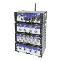
4 Modules
44 A04089_07_E00_02 HBM: public MX Modules
The following table gives the descriptions for all LED states.
System LED Description
Green System is error free
Red System error
Orange System is not ready; boot procedure is running
Orange flashing System is not ready; download is active
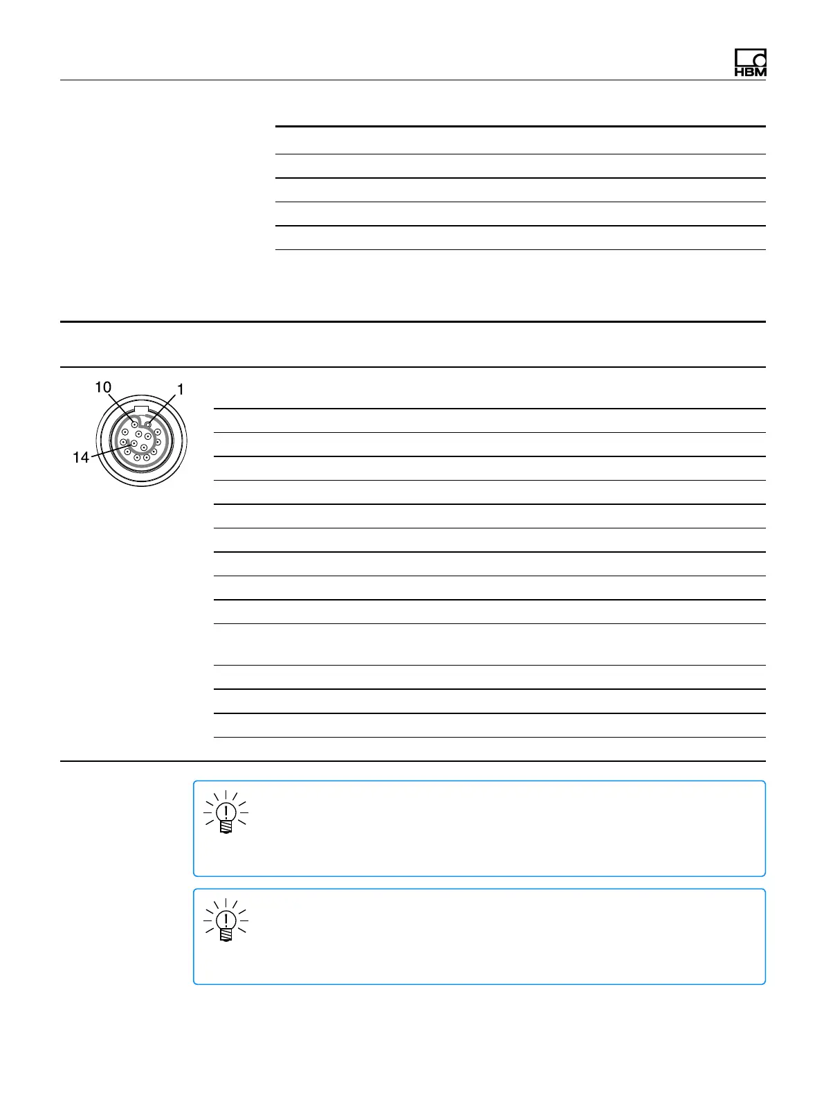
MX1615B-R pin assignments
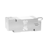
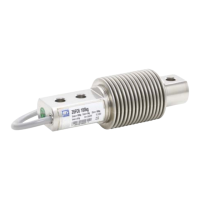
Connect sensors via the 14-pin ODU MINI-SNAP connectors.
Connector Pin Connection
Wire color
(1-KAB183 or 1-KAB184)
pin side of cable
1 Excitation (-)
jumper to pin 11
Black
2 Excitation (+) Blue
3 Voltage input 60 V (+) White/Black
4 Signal ground Red/Black
5 -- Pink/Black
6 -- Yellow/Black
7 Measurement signal (+) White
8 Measurement signal (-) Red
9 -- Brown
10 -- Yellow
11 Sense (-)
jumper to pin 1
Grey
12 Sense (+) Green
13 TEDS (-) Grey/Black
14 TEDS (+) Green/Black
Shield Shield --
NOTE
Pin assignment is different for Strain gage transducers, Resistance-based
measurements and Resistance-based measurements inputs. For more
information, refer to the wiring diagrams.
NOTE
Connection between pins 1 and 11 is necessary for all MX1615B-R transducers.
Note that the sensor connector must have a connection between pins 4 and 5 for
compatibility with other MX modules.