58 A04089_07_E00_02 HBM: public MX Modules
BUS LEDs Description
Green flashing Bus is error free; activity on CAN
Green Bus is error free; no activity on CAN
Orange flashing Intermittent bus errors (warning); activity
on CAN
Orange Intermittent bus errors (warning); no
activity on CAN
Red Bus error; CAN interface in Bus OFF
status
Connector LEDs Description
Green Channel is activated - no errors or failure
Orange BUS warning - intermittent or permanent
failure
Orange flashing Firmware update in progress
Red BUS error - data is lost, reduce number of
decoded and/or transmitted signals
Red flashing BUS off - no transmission or receiving
possible
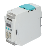
MX471B-R pin assignments
Connector PIN Description
Wire color
(1-KAB2109-2)
pin side of cable
1 CAN_SHLD (direct connected to chassis potential, capacitively
coupled to GND)
Yellow
2 -- Red
3 CAN_GND (Ground / 0V / V-) Black
4 CAN_H (dominant high) White
5 CAN_L (dominant low) Blue
NOTE
According to EMC requirements, Pin 1 can be connected to the shield of the CAN
cable. The integration of the module MX471B-R in the potential equalization is
highly recommended.