10
MPC Platinum Installation and Operation Manual
HT# 059085-00 F
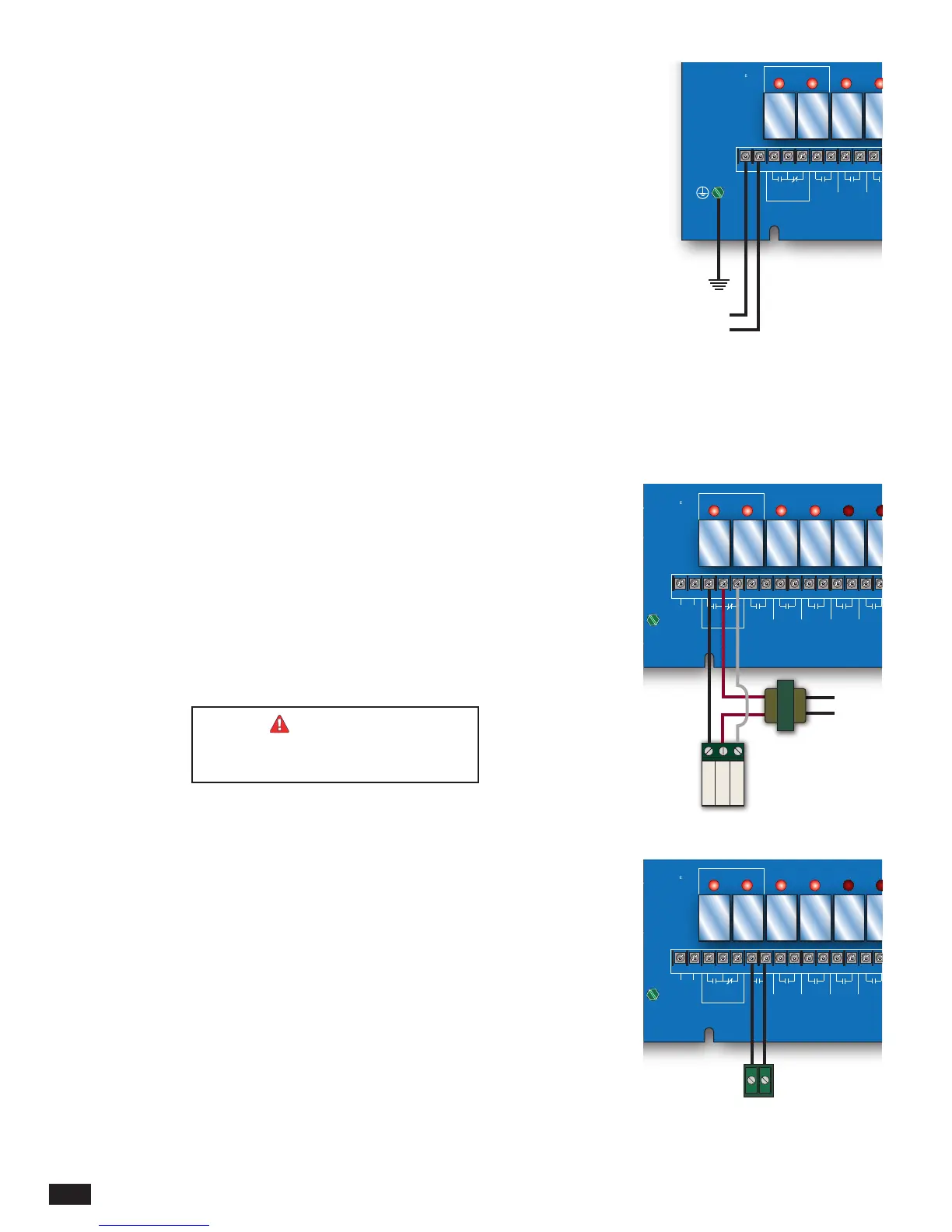
WIRING THE POWER
• If possible, provide a dedicated circuit breaker for the MPC Platinum. DO NOT connect
the MPC Platinum to a circuit breaker connected to high inductance devices such as
relays, pumps, fans, or motors.
• Bring the 120VAC 60Hz power wires through a bottom knockout (KO) of the enclosure.
• Class 1 voltages must enter the enclosure through a different knockout from any Class 2
voltage wiring.
• Connect the hot line to terminal marked LINE.
• Connect the neutral line to the terminal marked NEUT. DO NOT share neutrals. The
neutral line MUST come directly from the circuit breaker.
• Connect the green ground screw to earth ground. DO NOT use the neutral line as a
ground.
• Heat-Timer recommends the installation of a Surge Suppressor and a Power Switch
before the Power Line connection for safety and ease of service.
MADE IN U.S.A.
SAFETY
GROUND
MUST BE
CONNECTED
OUT
TEMP
AUX
INPUT 0
AUX
TEMP 0
AUX
TEMP 1
MENU FUNCTIONS
SELECT enters menus or accepts changes
ADJUST selects menu items or changes settings
BACK returns to previous menu
DAY selects next day
PREV./NEXT steps through output status
DAY
HELP NEXT
PRESS TO
SELECT
BACK
MON 12/01/2010 10:01Am
ADJUST
A1
A2
A3
A4
A5
A6
A7
A8
A9
A10
A11
A12
AUX
TEMP 2
DO NOT APPLY ANY VOLTAGE
TO SENSOR TERMINALS
A13
A14
A15
A16
A17
A18
NETWORK
PROVE
SHUTDOWN
SYSTEM
TEMP
BYPASS
ALL SENSORS MUST BE
GOLD SERIES SENSORS
INPUTS
ROUTE SENSOR AND AUXILIARY WIRES
THROUGH THIS KNOCKOUT ONLY
T
T
T
Cycle On 13/15
Cutoff = 55
o
F Day
OD = 31
o
F SYS = 138
o
F
AUTO
T
T
C O R P O R A T I O N
R
OUTPUT RATINGS:
120VAC, 6A RESISTIVE
1A PILOT DUTY
15A TOTAL
FOR ALL CIRCUITS
INPUT RATINGS:
115VAC 60Hz
30VA MAX
USE COPPER WIRE,
CLASS 1 WIRE ONLY
ENCLOSED
ENERGY
MANAGEMENT
EQUIPMENT
LISTED
99RA
SYSTEM
AUX
CLOCK
OPTION
1
OPTION
2
OPTION
3
BURNER
2 3 4 5
6 7 8 9 10 11
LINE
NEUTRAL
B R W
MOTORIZED
VALVE
OUTPUT SYS
OPTION
3
OPTION
2
OPTION
1
AUX
CLOCK
Earth
Ground
L
N
120 VAC
OUTPUT WIRING
• All of the MPC Platinum's outputs DO NOT SOURCE any power. If power is needed at
a specic output, a separate power source must be wired in series with the output.
• Each of the output relays can switch a 6A resistive at 120VAC load or a 1A inductive
load.
WIRING TO A MOTORIZED VALVE
• The MPC Platinum is capable of operating a boiler, a oating motorized valve, or both.
• The MPC Platinum output terminal R (5) is the Common. Wire it to the 24 VAC power
source (transformer).
• Connect the transformer's second wire to the actuator Common terminal.
• The MPC Platinum output terminal B (4) is the Normally Open (N.O.). Wire it to the
actuator Open terminal.
• The MPC Platinum output terminal W (6) is the Normally Closed (N.O.). Wire it to the
actuator Close terminal.
• The N.O. and N.C. contacts are dry contacts only. They do not source any power. The
transformer is the actuator power source.
WARNING
Switching to BYPASS during power
outages activates the Output and System.
MPC
Platinum
MADE IN U.S.A.
PREV.
(DEL)
SAFETY
GROUND
MUST BE
CONNECTED
OUT
TEMP
AUX
INPUT 0
AUX
TEMP 0
AUX
TEMP 1
MENU FUNCTIONS
SELECT enters menus or accepts changes
ADJUST selects menu items or changes settings
BACK returns to previous menu
DAY selects next day
PREV./NEXT steps through output status
DAY
HELP NEXT
PRESS TO
SELECT
BACK
MON 12/01/2010 10:01Am
ADJUST
A1
A2
A3
A4
A5
A6
A7
A8
A9
A10
A11
A12
AUX
TEMP 2
DO NOT APPLY ANY VOLTAGE
TO SENSOR TERMINALS
A13
A14
A15
A16
A17
A18
NETWORK
PROVE
SHUTDOWN
SYSTEM
TEMP
BYPASS
ALL SENSORS MUST BE
GOLD SERIES SENSORS
INPUTS
ROUTE SENSOR AND AUXILIARY WIRES
THROUGH THIS KNOCKOUT ONLY
T
T
T
Cycle On 13/15
Cutoff = 55
o
F Day
OD = 31
o
F SYS = 138
o
F
AUTO
T
T
C O R P O R A T I O N
R
OUTPUT RATINGS:
120VAC, 6A RESISTIVE
1A PILOT DUTY
15A TOTAL
FOR ALL CIRCUITS
INPUT RATINGS:
115VAC 60Hz
30VA MAX
USE COPPER WIRE,
CLASS 1 WIRE ONLY
ENCLOSED
ENERGY
MANAGEMENT
EQUIPMENT
LISTED
99RA
SYSTEM AUX
CLOCK
OPTION
1
2
BURNER
2 3 4 5
6 7 8 9 10 11 12 13 14 15
LINE
NEUTRAL
B R W
MOTORIZED
VALVE
OUTPUT SYS
OPTION
1
AUX
CLOCK
Common
Close
Open
Floating
Valve Actuator
Transformer
120 VAC
24 VAC
WIRING TO A BOILER
• The MPC Platinum s designed to operate a boiler, a oating motorized valve, or both.
• The BURNER output terminals are 7 and 8. They do not source any power. Wire the
burner output in series with the boiler limit circuit.
MPC
Platinum
MADE IN U.S.A.
PREV.
(DEL)
SAFETY
GROUND
MUST BE
CONNECTED
OUT
TEMP
AUX
INPUT 0
AUX
TEMP 0
AUX
TEMP 1
MENU FUNCTIONS
SELECT enters menus or accepts changes
ADJUST selects menu items or changes settings
BACK returns to previous menu
DAY selects next day
PREV./NEXT steps through output status
DAY
HELP NEXT
PRESS TO
SELECT
BACK
MON 12/01/2010 10:01Am
ADJUST
A1
A2
A3
A4
A5
A6
A7
A8
A9
A10
A11
A12
AUX
TEMP 2
DO NOT APPLY ANY VOLTAGE
TO SENSOR TERMINALS
A13
A14
A15
A16
A17
A18
NETWORK
PROVE
SHUTDOWN
SYSTEM
TEMP
BYPASS
ALL SENSORS MUST BE
GOLD SERIES SENSORS
INPUTS
ROUTE SENSOR AND AUXILIARY WIRES
THROUGH THIS KNOCKOUT ONLY
T
T
T
Cycle On 13/15
Cutoff = 55
o
F Day
OD = 31
o
F SYS = 138
o
F
AUTO
T
T
C O R P O R A T I O N
R
OUTPUT RATINGS:
120VAC, 6A RESISTIVE
1A PILOT DUTY
15A TOTAL
FOR ALL CIRCUITS
INPUT RATINGS:
115VAC 60Hz
30VA MAX
USE COPPER WIRE,
CLASS 1 WIRE ONLY
ENCLOSED
ENERGY
MANAGEMENT
EQUIPMENT
LISTED
99RA
SYSTEM AUX
CLOCK
OPTION
1
2
BURNER
2 3 4 5
6 7 8 9 10 11 12 13 14 15
LINE
NEUTRAL
B R W
MOTORIZED
VALVE
OUTPUT SYS
OPTION
1
AUX
CLOCK
Boiler