MPC Platinum Installation and Operation Manual
15
HT# 059085-00 F
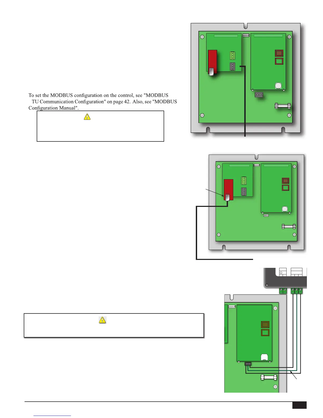
MODBUS RTU WIRING
• A MODBUS communication board and a CPU board with the
MODBUS software is required for proper MODBUS communication.
• Heat-Timer Platinum control MODBUS communication uses a
RS485 connection.
• Connect the MODBUS RS485 cable to the Communication Board's
RS485 socket. The Communication Board's RS485 socket has ‘A
(+)’, G (Ground), and ‘B (-)’ terminals. Polarity is observed,
• The cable length must not exceed 3500 feet.
• Must Connect the ground RS485 terminal (G) to the BMS RS485
Ground.
•
R
ALERT
DO NOT USE the RS485 Connector on the Motherboard
for MODBUS communication. Use the RS485 Connector
on the MODBUS Communication Board instead.
Motherboard
CPU Board
Connect Black RS485
to MODBUS Network
MODBUS
Communication
Board
INTERNET WIRING
ETHERNET CONNECTION TO MODEM
• Connect the Ethernet cable (provided) to the modem socket marked
Ethernet/LAN. Class 2 voltage wires must use a different knockout
from Class 1 voltage wires.
• Connect the other Ethernet cable end to the Communication board,
through the side knockout.
ETHERNET CONNECTION TO PLATINUM
CONTROL
• Bring the Ethernet line through one of the Platinum Enclosure side
knockouts. Class 2 voltage wires must use a different knockout from
Class 1 voltage wires.
• Connect the Ethernet cable to the Communication Board on the back
of the Platinum control. See "Platinum Internet Setup Manual".
Motherboard
CPU Board
Communication
Board
PLATINUM PANEL CONNECTED
TO THE INTERNET
Connect to Internet
CAT5/Ethernet Cable
Ethernet socket
connect to
Cat-5 cable
DHW ENERGY SAVER WIRING
• The DHW Energy Saver communicates all of its information to the Platinum control
using RS485 (3-wire connection).
• The DHW Energy Saver RS485 terminals are wired to the Platinum main board’s
RS485 (under the PCB board).
• Follow the wiring as per the graph on the right.
ALERT
DO NOT connect the DHW Energy Saver to the RS485 on the Platinum RI board.
Instead, connect the DHW Energy Saver RS485 to the Platinum main board.
• Maximum wiring length should not exceed 100 Feet. Use 18 gauge 2-conductor
shielded wire (#18). Connect the shield to the middle terminals on both of the RS485
connections. To eliminate communication errors, DO NOT splice the communication
cable wires.
• When connecting the DHW Energy Saver and a Platinum Extension to the same
connector, make sure to splice the cables externally before bringing them to the RS485
Plug Connector on the main Platinum Board. See "DHW Energy Saver Manual".
COM
3 4 5
A GND B
16VAC
1 2
~ ~
Use RS485
Communication
on the back of the
Platinum main board
PCB board
Shield
DHW Energy Saver
COM
3 4 5
A GND B
16VAC
1 2
~ ~
Use RS485
Communication
on the back of the
Platinum main board
PCB board
Shield
A(+)
G
B(-)
A(+)
G
B(-)
A(+)
G
B(-)
A(+)
G
B(-)