MPC Platinum Installation and Operation Manual
3
HT# 059085-00 F
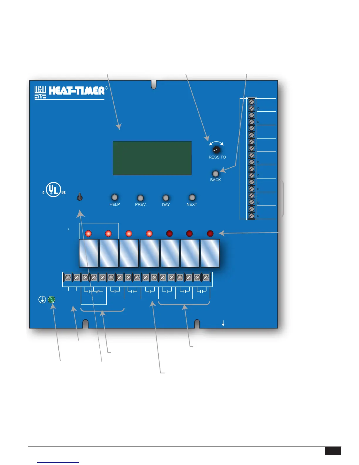
MPC PLATINUM FUNCTION CHART
MPC
Platinum
MADE IN U.S.A.
PREV.
(DEL)
SAFETY
GROUND
MUST BE
CONNECTED
OUT
TEMP
AUX
INPUT 0
AUX
TEMP 0
AUX
TEMP 1
MENU FUNCTIONS
SELECT enters menus or accepts changes
ADJUST selects menu items or changes settings
BACK returns to previous menu
DAY selects next day
PREV./NEXT steps through output status
DAY
HELP NEXT
PRESS TO
SELECT
BACK
MON 12/01/2010 10:01Am
ADJUST
A1
A2
A3
A4
A5
A6
A7
A8
A9
A10
A11
A12
AUX
TEMP 2
DO NOT APPLY ANY VOLTAGE
TO SENSOR TERMINALS
A13
A14
A15
A16
A17
A18
PROVE
SHUTDOWN
SYSTEM
TEMP
BYPASS
ALL SENSORS MUST BE
GOLD SERIES SENSORS
INPUTS
ROUTE SENSOR AND AUXILIARY WIRES
THROUGH THIS KNOCKOUT ONLY
T
T
T
Cycle On 13/15
Cutoff = 55
o
F Day
OD = 31
o
F SYS = 138
o
F
AUTO
T
T
C O R P O R A T I O N
R
OUTPUT RATINGS:
120VAC, 6A RESISTIVE
1A PILOT DUTY
15A TOTAL
FOR ALL CIRCUITS
INPUT RATINGS:
115VAC 60Hz
30VA MAX
USE COPPER WIRE,
CLASS 1 WIRE ONLY
ENCLOSED
ENERGY
MANAGEMENT
EQUIPMENT
LISTED
99RA
SYSTEM AUX
CLOCK
OPTION
1
OPTION
2
OPTION
3
BURNER
2 3 4 5
6 7 8 9 10 11 12 13 14 15 16 17
18
LINE
NEUTRAL
B R W
MOTORIZED
VALVE
OUTPUT SYS
OPTION
3
OPTION
2
OPTION
1
AUX
CLOCK
From heating system sensor
When closed, outputs
are turned off*
From Heat-Timer network
sensors**
Checks status of system
components*
From outdoor sensor
mounted in the shade
Red lights indicate when the
associated stage relay
is activated
Remote Communication
Option**
* DRY CONTACT ONLY
** Only available with the Remote Communications package
Depress the knob to move
forward through the menus and to
accept changes. To change a
setting's value, rotate the knob.
Depress the button to go back
through the menus
Digital display shows the cycle status,
outdoor cutoff, outdoor, and system temperatures.
To view and adjust settings, press the
Adjust/Select button.
From DHW Control*
Green Earth
Ground screw
120VAC
Power
BYPASS position runs
the output.
Valve and Burner
Outputs are active
when MPC requires
steam
Operates additional equipment based
on a separate Aux Schedule
OPTION outputs can be programmed
to operate additional equipment or
Internet Modem.
NETWORK
MSI CONNECTION
ON BACK