EasyManua.ls Logo

heat-timer ETV Platinum Plus - User Manual

heat-timer ETV Platinum Plus
60 pages
Print Icon
To Next Page IconTo Next Page
Loading...
INSTALLATION AND
OPERATION MANUAL
059305–00 REV. E
ETV PLATINUM PLUS
ELECTRONIC TEMPERING VALVE WITH SAFEGUARD

Table of Contents

Questions and Answers

  • D
    Denise PachecoAug 16, 2025
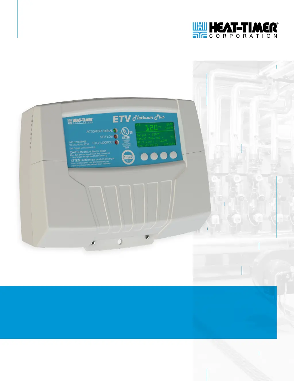
    How to troubleshoot no display or distorted display on heat-timer ETV Platinum Plus Control Unit?
    • E
      Eric HernandezAug 16, 2025
      To resolve a 'No display or distorted display' issue on your Heat-Timer ETV Platinum Plus Control Module: * First, verify that the ETV Platinum Plus Control Module is receiving power and that all power wiring is in good condition and properly connected. The module requires 120Vac power to terminals 1 and 2, and earth ground wiring to terminal 3. * Then, try turning the power to the ETV Platinum Plus Control Module off and then back on.
  • D
    Daniel DanielsAug 20, 2025
    Why does the outlet temperature fluctuate with my Heat-Timer ETV Platinum Plus?
    • S
      Sarah ThomasAug 20, 2025
      Outlet temperature fluctuations in the Heat-Timer ETV Platinum Plus system typically occur when the circulation pump isn't running constantly or the System Sensor isn't properly placed. Ensure the pump operates correctly, the System Sensor tip is in the flow stream, and the sensor is 1 to 3 feet from the ETV valve outlet.
  • D
    dawnalvarezAug 25, 2025
    What to do if my Heat-Timer Control Unit reads incorrect temperature?
    • G
      gonzalesrobinAug 25, 2025
      If your Heat-Timer Control Unit system reads an incorrect temperature, it might be due to: * A probe sensor that is not properly installed. Ensure the probe sensor is correctly placed in the flow of the water stream. * A defective sensor or ETV Platinum Plus Control Module. Disconnect the wires from the input terminals; the display should then read “Open”. If it doesn't, the device is defective and the ETV Platinum Plus Control Module should be replaced. If the control reads “Open” and the temperature difference is within 5°F, replace the sensor.
  • G
    Gina EstesAug 27, 2025
    What to do if heat-timer ETV Platinum Plus display shows sensor “Open”?
    • L
      Lisa DennisAug 27, 2025
      If the Heat-Timer Control Unit display shows sensor “Open”, it could be due to: * A disconnected sensor. Verify the sensor is properly connected to the ETV Platinum Plus Control Module. * A defective sensor, wires, or ETV Platinum Plus Control Module. Short the sensor input wires. The display should read “Short”. If the display still reads “Open”, the device is defective and the ETV Platinum Plus Control Module should be replaced. If the display reads “Short”, test the sensor wiring for continuity and replace the sensor/wiring if necessary.
  • K
    Kevin KimAug 31, 2025
    What to do if heat-timer ETV Platinum Plus display shows sensor “Short”?
    • S
      Shawn JonesAug 31, 2025
      If the Heat-Timer Control Unit display shows sensor “Short”, it could be due to a defective sensor, wires, or ETV Platinum Plus Control Module. To resolve this: * Remove the sensor wires from the input terminals. The display should read “Open”. * If the display still reads “Short”, the device is defective and the ETV Platinum Plus Control Module should be replaced. * If the display reads “Open”, test the sensor wiring for continuity. Replace the sensor/wiring if necessary.
  • B
    Benjamin GrantSep 3, 2025
    What to do if Heat-Timer Control Unit display shows IP DUPE?
    • W
      William CastilloSep 4, 2025
      If the Heat-Timer Control Unit displays 'IP DUPE', it means two controls have the same IP address. To resolve this, change the second control’s Internet ID to a unique value and configure the Port Forwarding accordingly.
  • B
    Brandon RosalesNov 11, 2025
    What to do if Heat-Timer ETV Platinum Plus Control Module doesn't move the Floating Motorized Valve?
    • R
      rhillNov 11, 2025
      If the Heat-Timer ETV Platinum Plus Control Module isn't moving the Floating Motorized Valve, it could be due to a few reasons: 1. **Valve wiring defective:** Ensure all wiring is in good condition and properly connected. Check that the voltage at the Actuator power terminals is between 20–24Vac. Voltages outside this range can prevent movement or damage the Actuator. 2. **Valve modulating signal incorrect:** Verify the ETV modulating signal is set to 0–10V to match the Actuator’s signal. Use a DC voltmeter to measure the modulation signal on terminals 13 and 15. If the Modulation Output % was at 40%, the signal should read 4Vdc. If not, the ETV control may be damaged, and the ETV Platinum Plus should be replaced. 3. **Actuator manual override engaged:** Make sure the actuator is not s...

Summary

02 DETAILED OPERATION

OVERVIEW

Provides a general introduction to the ETV Platinum Plus Electronic Tempering Valve and its function.

ETV OPERATING CONCEPT

Explains how the ETV Platinum Plus controls a mixing valve to maintain a temperature setpoint by mixing hot and cold water.

ETV PLATINUM PLUS INPUTS

Details the various inputs available for the ETV Platinum Plus, including sensors and switches.

ETV PLATINUM PLUS OUTPUTS

Describes the outputs of the ETV Platinum Plus, including actuator signals and HTLV lockout.

03 SPECIFICATIONS

ETV PLATINUM PLUS CONTROL MODULE

Lists the technical specifications for the ETV Platinum Plus control module, including voltage, dimensions, and interface.

ETV PLATINUM PLUS ACTUATOR

Details the specifications for the ETV Platinum Plus actuator, including voltage input, power consumption, and weight.

ETV PLATINUM PLUS VALVE BODY

Provides specifications for the ETV Platinum Plus valve body, such as materials, temperature, and pressure ratings.

ETV PLATINUM PLUS STAINLESS STEEL VALVE SIZING

Offers sizing information for ETV Platinum Plus stainless steel valves based on pressure drop and flow rate.

HTLV VALVE AND ACTUATOR SPECIFICATIONS

Specifies the technical details for the HTLV valve and actuator, including electrical, performance, and dimensional data.

04 INSTALLATION INSTRUCTIONS

DESIGN CONSIDERATIONS

Highlights key design factors to consider before installing the ETV Platinum Plus system.

PIPING AND VALVE INSTALLATION

Covers general piping guidelines, HTLV piping, and the physical installation of the ETV valve.

MOUNTING THE ETV PLATINUM PLUS

Details the mounting procedures for the ETV Platinum Plus control module and its display.

WIRING THE ETV PLATINUM PLUS

Provides comprehensive instructions for all wiring aspects, including power, actuator, inputs, and communications.

VALVE ACTUATOR SETTINGS AND CALIBRATION

Guides on configuring dip switches and calibrating the valve actuator based on installation type.

05 PIPING DIAGRAMS

06 DISPLAY AND PROGRAMMING

DISPLAY AND VARIABLE-FUNCTION BUTTONS

Explains the ETV Platinum Plus display layout and the functions of its variable buttons.

DISPLAY ICONS AND MESSAGES

Lists and describes the icons and messages that can appear on the ETV Platinum Plus display.

ALARM MESSAGES

Details the various alarm messages the ETV Platinum Plus can display and their triggers.

INITIAL PROGRAMMING OF THE ETV PLATINUM PLUS

Guides the user through the initial setup and programming of the ETV Platinum Plus upon first power-up.

CONTROL MODE

Explains the different control modes available (ETV, HTLV, ETV+HTLV) for the ETV Platinum Plus.

SETPOINT

Details how to set and manage the desired mixed valve outlet temperature for normal operation.

MAINTENANCE MENU

Covers the maintenance functions for critical system behavior adjustments and viewing alarm history.

LOCKOUT MENU

Describes how to access and reset system lockouts, typically related to HTLV conditions.

07 TROUBLESHOOTING

08 NOTES

09 WARRANTY

heat-timer ETV Platinum Plus Specifications

General IconGeneral
Brandheat-timer
ModelETV Platinum Plus
CategoryControl Unit
LanguageEnglish

Related product manuals