059305–00 REV. E
HEAT-TIMER CORP.
|
29
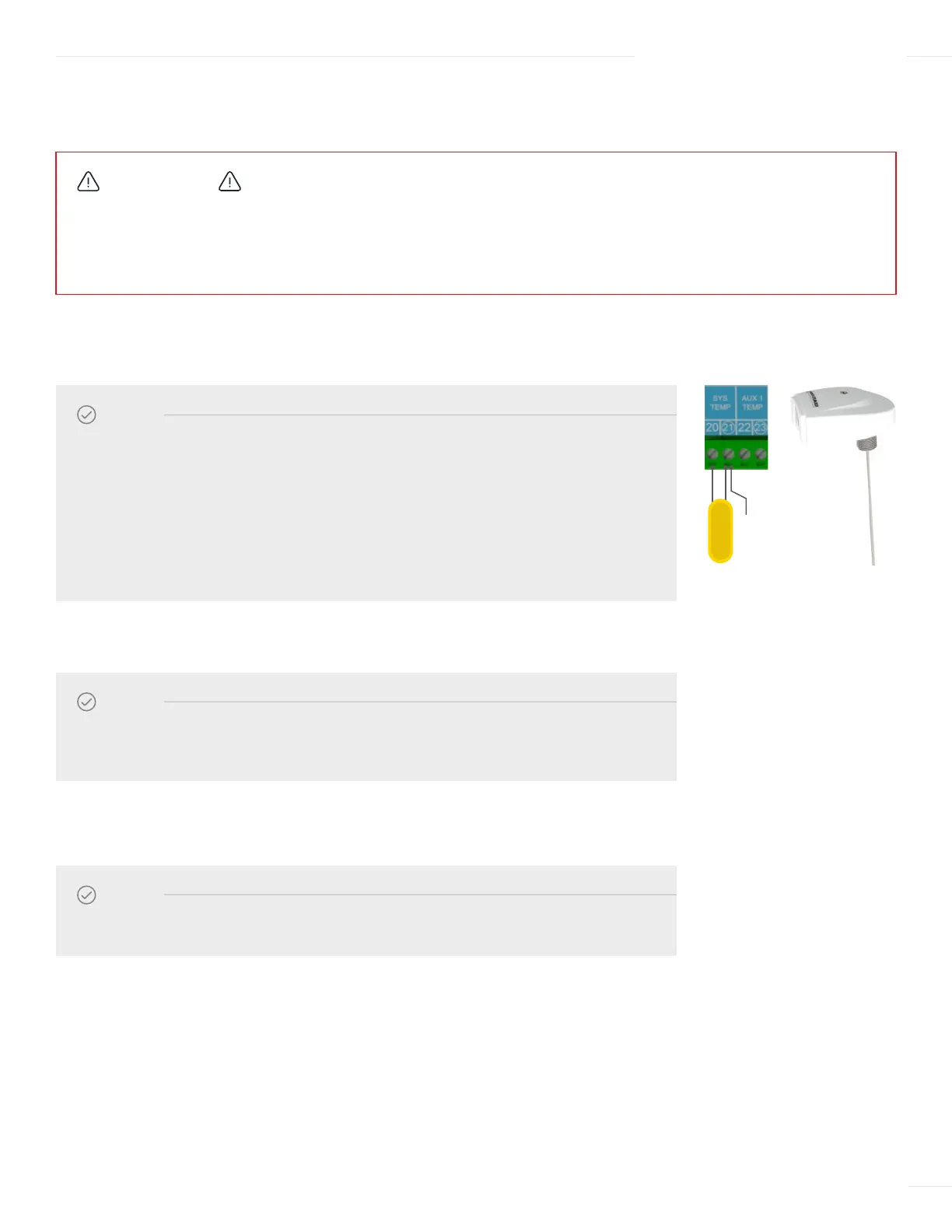
1 Run the System Sensor wires through a knockout located on the bottom of the ETV enclosure.
2 Connect the System Sensor wires to terminal 20 and 21 on the ETV module.
3 Connect the shield to terminal 21 on the ETV module.
04 INSTALLATION INSTRUCTIONS
NOTE
• The System Temperature Sensor must be connected for the system to operate. Refer
to page 5 for a description of the sensor.
• For acceptable sensor locations, refer to the piping diagram Figure 2 on page 12.
• Due to the internal logic and performance of the ETV Platinum Plus, the use of a
standard brass tube thermistor will affect the accuracy and performance of the
control and is not recommended. The use of Probe Sensor (Heat-Timer P/N
904222–00) supplied with the module is strongly recommended.
NOTE
The sensor wires can be extended up to 500 feet (152.5 meters) using an 18 AWG
shielded 2-conductor cable (Heat-Timer P/N 703001–01 or equivalent #18/2 cable).
NOTE
Do not connect the shield at the sensor end.
INPUT WIRING
WIRING THE SYSTEM TEMPERATURE SENSOR
SHIELD
SYSTEM
SENSOR
CAUTION
To avoid damage to the ETV Platinum Plus, NO VOLTAGE can be applied to the ETV Platinum Plus input terminals.
Class 2 voltage wiring (low-voltage sensor and communication wires) must use a different enclosure knockout and conduit
than any Class 1 voltage wiring.