34
|
HEAT-TIMER CORP.
059305–00 REV. E
04 INSTALLATION INSTRUCTIONS
VALVE ACTUATOR SETTINGS AND CALIBRATION
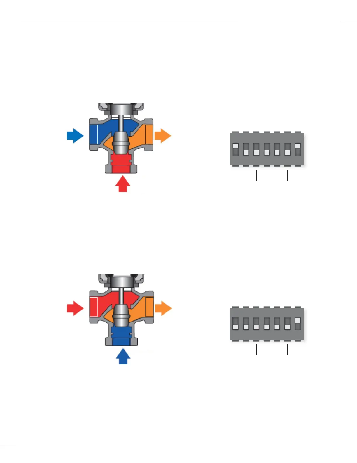
The position of the Actuator Dip Switch 1 and whether the Capacitor jumper is used or removed will be determined by how the valve
is installed. See Figure 13 for location of the Actuator Dip Switch and Capacitor Jumper.
Set Dip Switch 1 to ON/HOT B if the ETV valve is piped with the “Default” configuration of COLD in Port A and HOT in Port B
The Capacitor Jumper if applicable must remain as installed by the factory. On loss of power the actuator will push the valve stem
downward to the full COLD position.
Set Dip Switch 1 to OFF/HOT A if the ETV valve is piped with the “Alternate” configuration of HOT in Port A and COLD in Port B
The Capacitor Jumper if applicable must be removed. On loss of power the actuator will pull the valve stem upward to the full
COLD position.
DIP SWITCH 1 = OFF
OFF
HOT BHOT A
SEQ
5–10, 6–100–5, 2–6
INCMOD
2–100–10
4–20mA
MANAUTO
ON
1 2 3 4 5 6 7
COLD PORT
A
MIXED PORT
AB
HOT PORT
B
OFF
HOT BHOT A
SEQ
5–10, 6–100–5, 2–6
INCMOD
2–100–10
4–20mA
MANAUTO
ON
1 2 3 4 5 6 7
HOT PORT
A
MIXED PORT
AB
COLD PORT
B
DIP SWITCH 1 = ON