059305–00 REV. E
HEAT-TIMER CORP.
|
17
MOUNTING THE ACTUATOR TO THE ETV VALVE
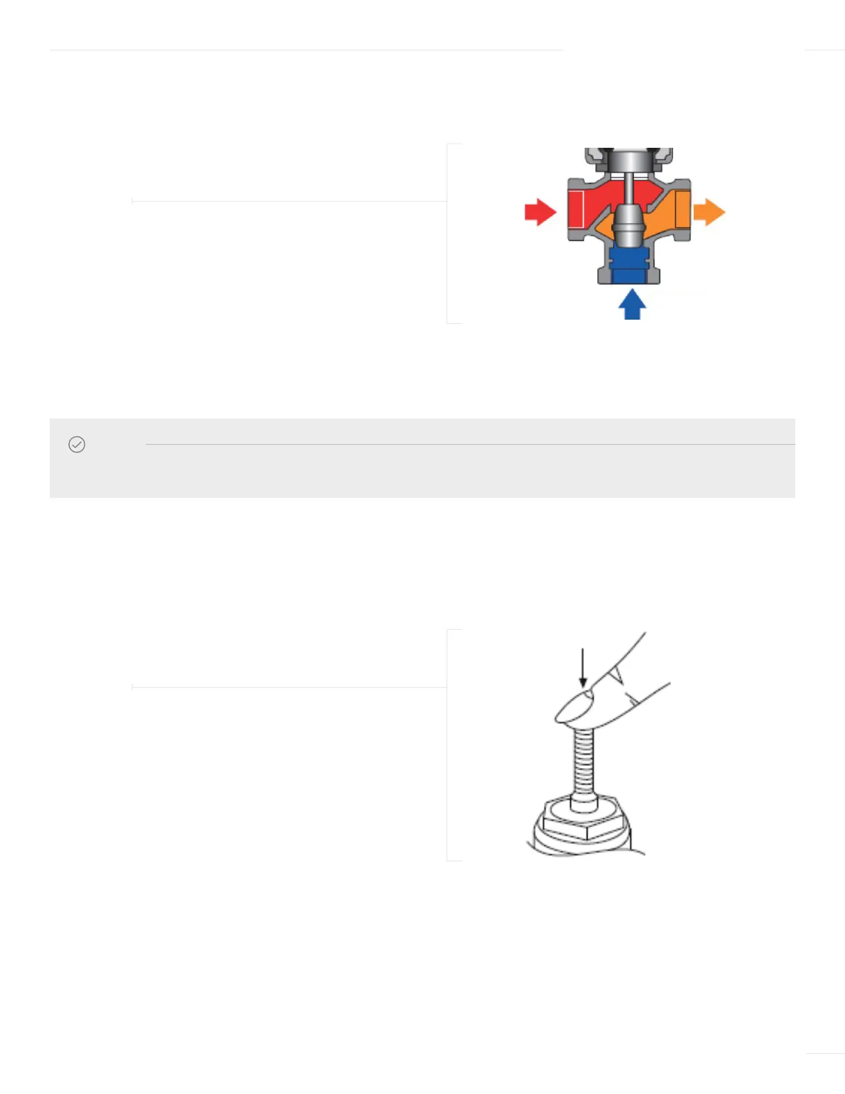
1 Before mounting the Actuator to the ETV valve, manually close the ETV valve by pushing down on the valve stem as shown
in Figure 6.
2 Before mounting the Actuator to the ETV valve, manually lower the Actuator as shown in Figure 7.
a The Manual Tab to place the Actuator in Manual Override mode.
b Turn the Manual Tab counter-clockwise to drive the threaded shaft to the full lower position.
c Raise the Manual Tab to place the Actuator in Normal Operation mode.
2 Piping the valve as shown below is considered the “ALTERNATE” configuration.
Ensure to follow the port letter designation or the valve flow direction label.
3 Reference pages 30 through 32 for recommended system piping of the ETV valve.
04 INSTALLATION INSTRUCTIONS
FIGURE 5
“ALTERNATE” ETV VALVE CONFIGURATION
NOTE
Reference page 29 for Dip Switch settings based on valve installation configuration.
FIGURE 6
MANUALLY CLOSING THE ETV VALVE
HOT PORT
A
MIXED PORT
AB
COLD PORT
B