24
|
HEAT-TIMER CORP.
059305–00 REV. E
04 INSTALLATION INSTRUCTIONS
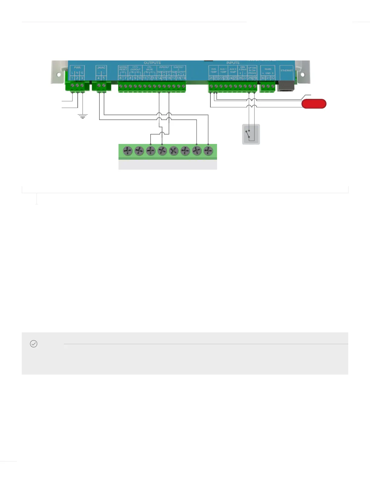
WIRING THE ACTUATOR—SINGLE-VALVE APPLICATION
FIGURE 10
ACTUATOR WIRING FOR A SINGLE ETV VALVE APPLICATION
1 Run the wiring through a knockout located on the bottom of the ETV Platinum Plus enclosure to the Actuator terminal block.
Use a Philips screwdriver and remove the actuator cover.
2 Connect the Actuator voltage signal wire from Actuator terminal (Y) to terminal 16 on the ETV module.
3 Connect the Actuator ground wire from Actuator terminal (M) to terminal 14 on the ETV module.
4 Connect 24Vac power from the ETV Platinum Plus module to the Actuator:
a Run the Actuator’s power wires through a knockout located on the bottom of the ETV enclosure.
b Connect the Actuator power wire from Actuator terminal (L1) to terminal 4 on the ETV module.
c Connect the Actuator power wire from Actuator terminal (Ln) to terminal 5 on the ETV module.
5 To optionally connect 24Vac power from the External Transformer Kit to the Actuator:
a Connect the first Actuator’s (L1) and (Ln) terminals to the transformer’s 24Vac terminals.
NOTE
The ETV can provide 24Vac power to a single Actuator. As an alternative, External Transformer Kit (Heat-Timer
P/N 950023–00) can be used to provide power to the Actuator.
HTC ACTUATOR ACCEPTS
0–10 VOLTAGE SIGNAL
SYSTEM SENSOR
SHIELD
V+ MU Y1 LnY Y2 L1
120 VAC
Earth ground
120 VAC
24 VAC
Actuator
Power
0–10V Voltage
Modulating Signal
L
N
FLOW SWITCH