14
|
HEAT-TIMER CORP.
059305–00 REV. E
GENERAL PIPING GUIDELINES
The following guidelines must be observed when piping the system.
1 All piping, including the piping of the ETV valve body, must meet or exceed local, state, and/or federal guidelines, codes,
and regulations.
2 Support all piping using hangers. DO NOT support piping by the unit or its components.
3 Use isolation valves (as shown in Figure 2) to isolate system components.
4 Use unions (as shown in Figure 2) to allow for servicing and, if required, removal of the ETV valve and sensors.
5 Include drain valves (as shown in Figure 2) to assist in servicing of the ETV valve and sensors.
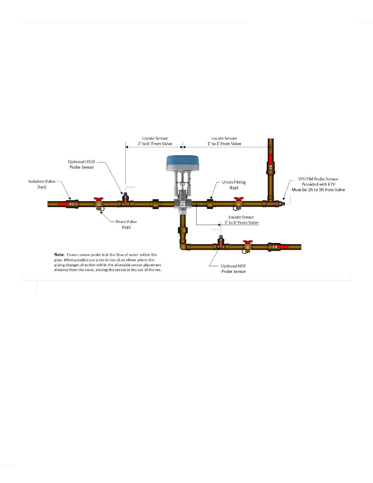
SENSOR PROBE LOCATIONS
Sensor probes must be installed within the flow of water in the pipe (see Figure 2). When possible, use a tee fitting rather than an
elbow fitting where the piping changes direction within the allowable sensor placement distance from the valve. The sensor probe is
then placed in the run of the tee fitting as shown as the System Sensor Probe in Figure 2.
When installing the probe sensor in a tee fitting, perpendicular to a run of piping, the tip of the probe sensor should be position at
the centerline of the piping (see optional HOT or COLD probe sensor in Figure 2). This may require a nipple and coupling in addition
to the tee fitting.
Refer To “ETV Platinum Plus Inputs” on page 5 for more information.
HTLV (HIGH TEMP LIMIT VALVE) PIPING
The optional HTLV is typically piped between the hot water source (a storage tank or boiler coil) and the Hot inlet of the ETV valve.
For an optional HTLV location, refer to “Piping Diagrams” on page 36.
FIGURE 2
PIPING GUIDELINES
04 INSTALLATION INSTRUCTIONS