059305–00 REV. E
HEAT-TIMER CORP.
|
25
04 INSTALLATION INSTRUCTIONS04 INSTALLATION INSTRUCTIONS
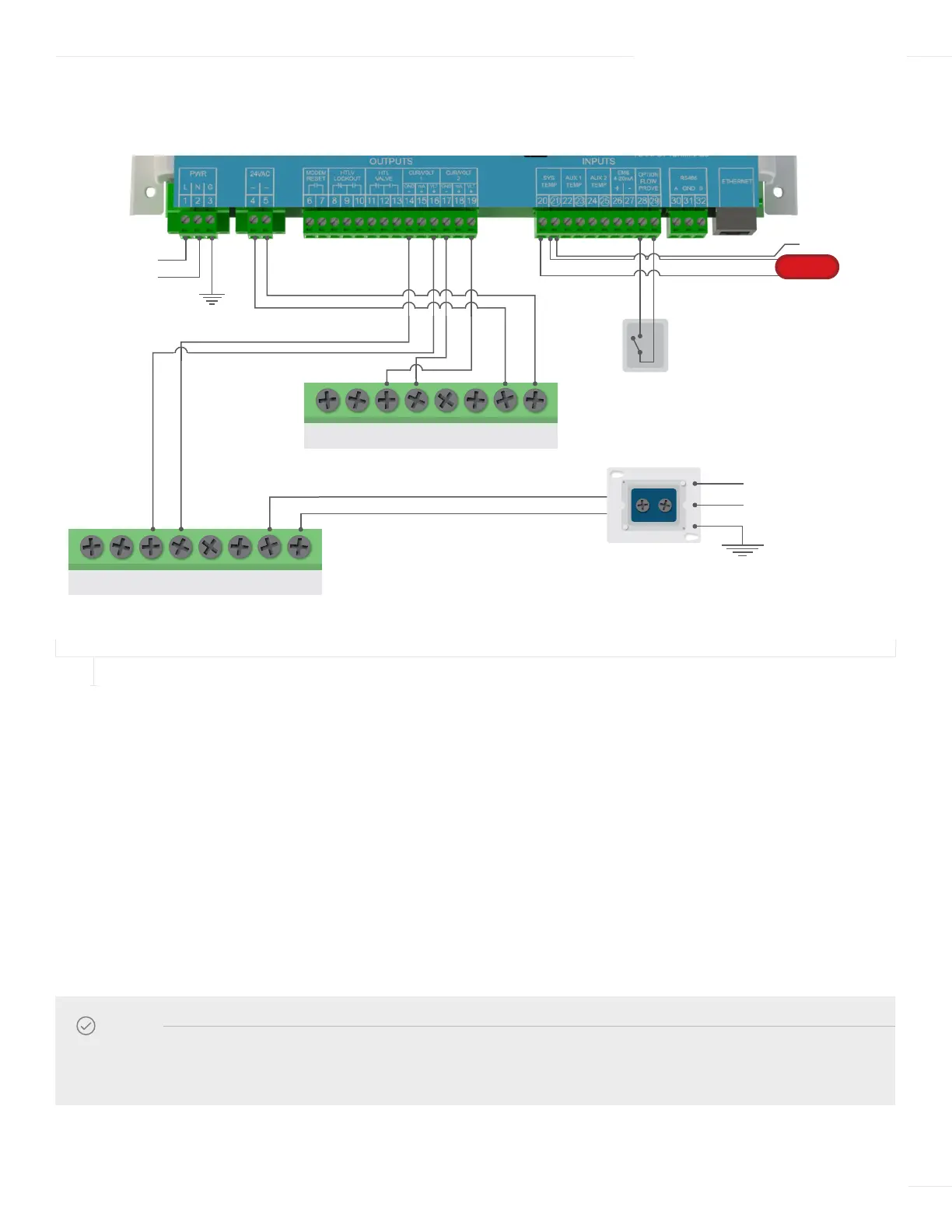
WIRING THE ACTUATOR—TWO-VALVE APPLICATION
FIGURE 11
ACTUATOR WIRING FOR A DUAL ETV VALVE APPLICATION
1 Connection of the first Actuator:
a Run the wiring through a knockout located on the bottom of the ETV enclosure to the Actuator terminal block.
b Connect the Actuator voltage signal wire from Actuator terminal (Y) to terminal 16 on the ETV module.
c Connect the Actuator ground wire from Actuator terminal (M) to terminal 14 on the ETV module.
2 Connect the second Actuator:
a Run the wiring through a knockout located on the bottom of the ETV enclosure to the Actuator terminal block.
b Connect the Actuator voltage signal wire from Actuator terminal (Y) to terminal 19 on the ETV module.
c Connect the Actuator ground wire from Actuator terminal (M) to terminal 17 on the ETV module.
NOTE
The ETV can only provide 24Vac power to a single Actuator. An external 24V transformer kit is required to provide power
to the second Actuator. The external 24V is provided when a valve/actuator kit is ordered.
0–10V Voltage
Modulating Signal
0–10V Voltage
Modulating Signal
HTC ACTUATOR ACCEPTS
0–10 VOLTAGE SIGNAL
HTC ACTUATOR ACCEPTS
0–10 VOLTAGE SIGNAL
SYSTEM SENSOR
SHIELD
V+ MU Y1 LnY Y2 L1
V+ MU Y1 LnY Y2 L1
120 VAC
Earth ground
24 VAC
Actuator
Power
L
N
FLOW SWITCH
TRANSFORMER
120
VAC
N
L
Earth Ground