16
|
HEAT-TIMER CORP.
059305–00 REV. E
ETV VALVE INSTALLATION
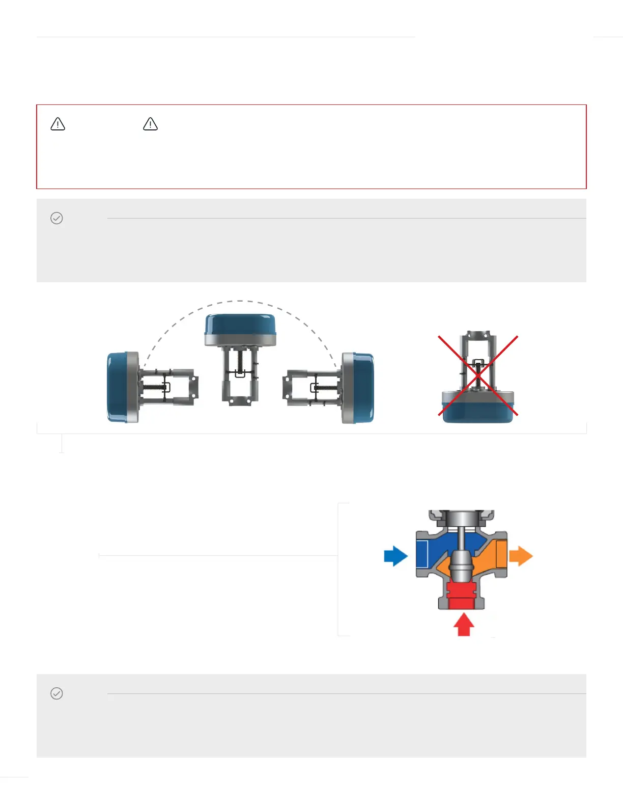
1 Piping the valve as shown below is considered
the “DEFAULT” configuration.
Ensure to follow the port letter designation or the valve flow direction label.
04 INSTALLATION INSTRUCTIONS
CAUTION
Use a two-wrench method (using one wrench to prevent the valve body from turning or twisting) when tightening piping
onto the valve body connections. Failure to support the valve body in this manner may cause damage to the valve body,
or result in the “B” port coming loose, resulting in water leakage.
NOTE
The valve and actuator can be mounted vertically (upright) or horizontally. DO NOT mount the valve and actuator upside
down. Leave at least 12 inches (30.5cm) service clearance on all sides between the valve/ actuator and any objects (walls,
pipes, controls, etc.).
NOTE
The ETV valve body can be oriented in such a way that the COLD Port A and HOT Port B are interchangeable to
accommodate existing piping. In this “alternate” configuration Port A becomes the HOT port and Port B becomes the
COLD port.
FIGURE 3
MOUNTING OF THE ETV VALVE AND ACTUATOR
FIGURE 4
“DEFAULT” ETV VALVE CONFIGURATION
COLD
PORT A
MIXED
PORT AB
HOT
PORT B