28
|
HEAT-TIMER CORP.
059305–00 REV. E
1 Connect one of the 24Vac transformer outputs to the actuator COMMON terminal on Terminal Block F of the Motorized Ball Valve.
2 Connect the second 24Vac transformer output to the HTLV Common terminal (12) on the ETV module.
3 Connect the HTLV normally closed (NC) terminal (11) on the ETV module to the Motorized Ball Valve actuator CLOSE terminal on
Terminal Block F
4 Connect the HTLV normally open (NO) terminal (13) on the ETV module to the Motorized Ball Valve actuator OPEN terminal on
Terminal Block F.
04 INSTALLATION INSTRUCTIONS
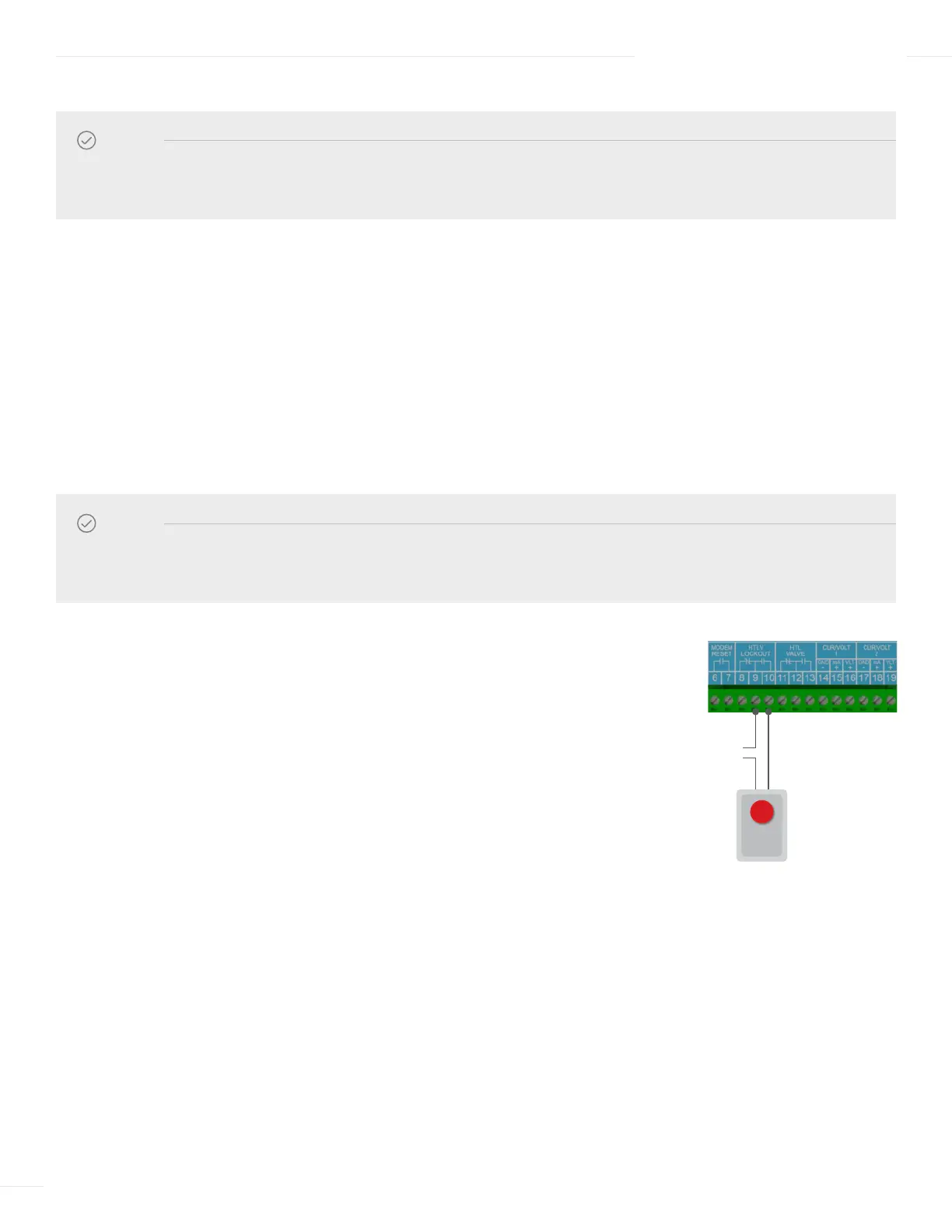
WIRING THE HTLV LOCKOUT ALARM (OPTIONAL)
1 Run the alarm wire and the external power source wire through knockouts located on the
bottom of the ETV enclosure.
2 To connect a N.O. alarm device (requires switch closure to trigger):
a Connect the alarm device wire to terminal 9 on the ETV module.
b Connect the external power source wire to terminal 8 on the ETV module.
c Connect the other alarm device wire to the external power source.
3 To connect a N.C. alarm device (requires switch open to trigger):
a Connect the alarm device wire to terminal 10 on the ETV module.
b Connect the external power source wire to terminal 9 on the ETV module.
c Connect the other alarm device wire to the external power source.
120 VAC
Vis-U-Alarm
NOTE
Prior to wiring of the Motorized Ball Valve actuator reference the Motorized Ball Valve installation manual—059434–00
for detail instructions on the removal and re-installation of the actuator cover.
NOTE
The ETV Platinum Plus does not source power to the HTLV Lockout terminals. An external power source is required and
must be connected in series as shown in the diagram. Refer to “HTLV Lockout Output” on page 6 for information.