30
|
HEAT-TIMER CORP.
059305–00 REV. E
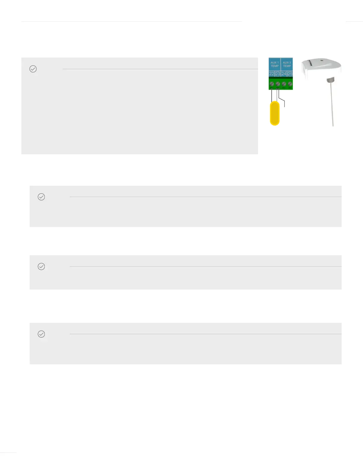
1 To connect an Auxiliary temperature sensor:
a Run the sensor wires through a knockout located on the bottom of the ETV enclosure.
b Connect the sensor wires to terminal 22 and 23 on the ETV module.
c Connect the shield to terminal 23 on the ETV module.
2 To connect a second Auxiliary temperature sensor:
a Run the sensor wires through a knockout located on the bottom of the ETV enclosure.
b Connect the sensor wires to terminal 24 and 25 on the ETV module.
c Connect the shield to terminal 25 on the ETV module.
04 INSTALLATION INSTRUCTIONS
NOTE
• No voltage can be applied to terminals 22 and 23 or terminal 24 and 25.
• Auxiliary inputs can be configured as temperature sensors or as switch sensors.
When configured as a switch sensor, it must be connected to a device that provides
an open or close (short) only.
• Standard brass tube sensors (Heat-Timer P/N 904220–00) can be used in a well if
the temperature sensor is only monitoring the temperature. However, the standard
brass tube sensor in a well is not recommended when using the Feed Forward
function (refer to “Return Comp.” on page 44). The use of Probe Sensor (Heat Timer
P/N 904222–00) is strongly recommended for the Feed Forward function.
NOTE
The sensor wires can be extended up to 500 feet (152.5 meters) using an 18 AWG shielded 2-conductor cable
(Heat-Timer P/N 703001–01 or equivalent #18/2 cable).
NOTE
The sensor wires can be extended up to 500 feet (152.5 meters) using an 18 AWG shielded 2-conductor cable
(Heat-Timer P/N 703001–01 or equivalent #18/2 cable).
NOTE
Do not connect the shield at the sensor end.
WIRING AUX INPUTS—SENSORS OR SWITCHES (OPTIONAL)
SHIELD
SYSTEM
SENSOR