059305–00 REV. E
HEAT-TIMER CORP.
|
31
04 INSTALLATION INSTRUCTIONS
3 To connect an Auxiliary switch:
a Run the switch wires through a knockout located on the bottom of the ETV enclosure.
b Connect the switch wires to terminal 22 and 23 on the ETV module.
4 To connect a second Auxiliary switch:
a Run the switch wires through a knockout located on the bottom of the ETV module.
b Connect the switch wires to terminal 24 and 25 on the ETV module.
NOTE
The sensor wires can be extended up to 500 feet (152.5 meters) using an 18 AWG shielded 2-conductor cable
(Heat-Timer P/N 703001–01 or equivalent #18/2 cable).
NOTE
The sensor wires can be extended up to 500 feet (152.5 meters) using an 18 AWG shielded 2-conductor cable
(Heat-Timer P/N 703001–01 or equivalent #18/2 cable).
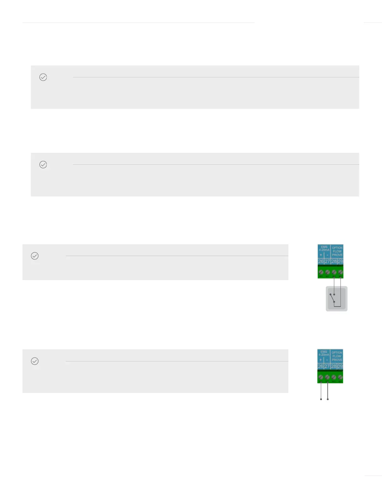
WIRING THE FLOW PROVE (OPTIONAL)
1 Run the Flow Prove wires through a knockout located on the bottom of the ETV enclosure.
2 Connect one wire to terminal 28 on the ETV module.
3 Connect the other wire to terminal 29 on the ETV module.
WIRING THE 4–20MA REMOTE SETPOINT
(OPTIONAL)
1 Run the 4–20mA Setpoint wires through a knockout located on the bottom of the ETV enclosure.
2 Connect the positive (+) wire to terminal 26 on the ETV module.
3 Connect the negative (–) wire to terminal 27 on the ETV module.
PROVE
NOTE
Refer to “Flow Prove” on page 5 for information.
NOTE
The ETV Platinum Plus does not source power to the 4–20mA terminals. The EMS system must
provide the excitation voltage. Refer to “4–20mA Remote Setpoint” on page 6 for information.
EMS SOURCES
VOLTAGE
+ –