MPC Platinum Installation and Operation Manual
9
HT# 059085-00 F
SENSOR INSTALLATION
OUTDOOR SENSOR INSTALLATION
Only use the Heat-Timer sensor included with the unit (HT# 904220-00).
• Locate the sensor in the shade on the north side of the building. The sensor
should never be in direct sunlight.
• Be sure the location is away from doors, windows, exhaust fans, vents, or other
possible heat or cool sources.
• The sensor should be mounted approximately 10’ feet above ground level.
• Adhere the Outdoor Label provided to the back of the sensor base.
• Use the Enclosure Base bottom knockout for the conduit. Use the locknut to hold
the conduit and enclosure base together. Screw the cover to the base.
• Make sure to seal around the sensor enclosure and wall except from the bottom.
• The sensor wires can be extended up to 500’ using shielded 2-conductor cable
(HT# 703001-01) (#18/2). Do not connect the shield at the sensor. However,
connect it at the control using the terminal marked with an “O”.
• Do not run sensor wires in conduit with line voltage wiring.
ALERT
Determining the proper location for the Outdoor Sensor is very important. The MPC Platinum will
base the heat on the outdoor temperature information it receives from this location. If the sensor is in
the sun, or covered with ice, its reading will be different from the actual Outdoor temperature (OD).
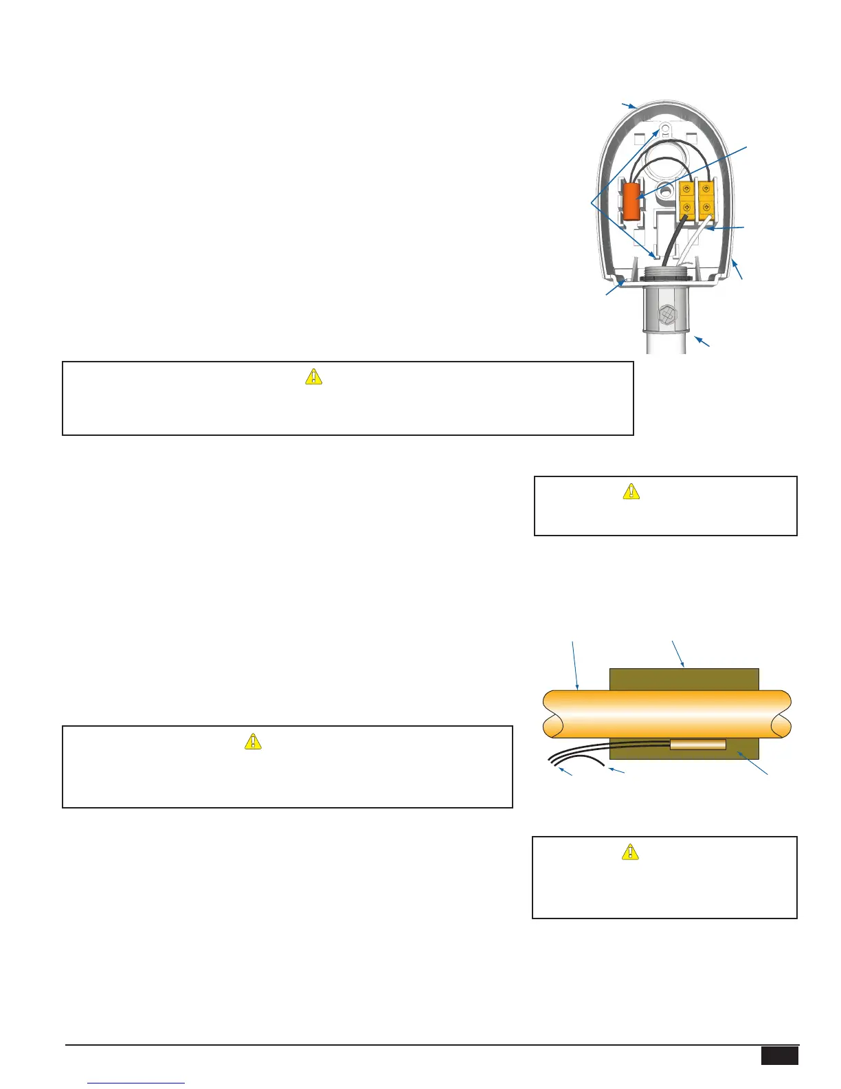
Outdoor Sensor
snap-in location
Shield
not connected
Conduit
Outdoor Label
on back of Sensor
Mounting
screws
location
Seal around
sensor and wall
Outdoor
drip-hole
HEATING SYSTEM SENSOR (HSS) INSTALLATION
• Install the sensor at one of the following locations:
The ideal location for the HSS is on the furthest radiator in the system. This
radiator is usually the hardest to heat.
The sensor may be located on the furthest return riser. However, the sensor
MUST be above the boiler water line (on a dry return).
• Only use the sensor provided with the control. If you are replacing an earlier
Gold model Heat-Timer, it is NOT necessary to upgrade the sensor.
• Strap the HSS to the pipe using the tie-wraps provided with the outdoor sensor.
Then wrap insulation around the sensor and pipe to achieve the highest accuracy.
• The sensor wires can be extended up to 500' using a shielded 2-conductor cable
(HT# 703001-01) (#18/2).
• Do not connect the shield at the sensor. However, connect it at the control using
the terminal marked with an “O”.
• Do not run sensor wires in conduit or trough with line voltage wiring.
ALERT
If the HSS cannot sense the system is full of steam, the MPC Platinum
will not provide comfortable heat levels. Be sure the HSS is located on
a properly vented pipe that cannot easily be isolated from the system.
ALERT
NEVER Install the HSS between the
condensate receiver and the boiler.
Shield
Immersion Well
3/8" ID 1/2" NPT
Immersion Heating System Sensor
Common Supply Pipe
Heating System
Sensor
Sensor Probe
Common Supply Pipe
Strap-On Heating System Sensor
Pipe Insulation
Sensor Probe
Shield
Connect
To control
Using a Pressutrol instead of the HSS
• Heat-Timer MPC Platinum control requires the use of a HSS. However, if a
good location for the HSS is not possible, it is acceptable to install a Pressuretrol
Adaptor Kit (HT# 900043-00) that connects to the boiler operating pressuretrol.
In this case, the system may not be as efcient as when using the HSS and the
Thermal Lockout feature will not be available..
ALERT
The use of the Pressuretrol Adaptor Kit
(HT# 900043-00) may reduce the system
operating efciency.