MPC Platinum Installation and Operation Manual
41
HT# 059085-00 F
MODBUS COMMUNICATION FEATURES
The MPC Platinum BUS (with MODBUS RTU connections) has many features and benets.
• Boiler and Sensor status, values, and settings. Provides “Live” status and editing capability of Platinum control settings and values
from the MODBUS network.
• The Data collected can be used to create a historical log, and trigger alarms.
MODBUS RTU COMMUNICATION CONFIGURATION
• If the Platinum control is purchased with or upgraded to a MODBUS communication, the
following settings must be congured to guarantee proper communication.
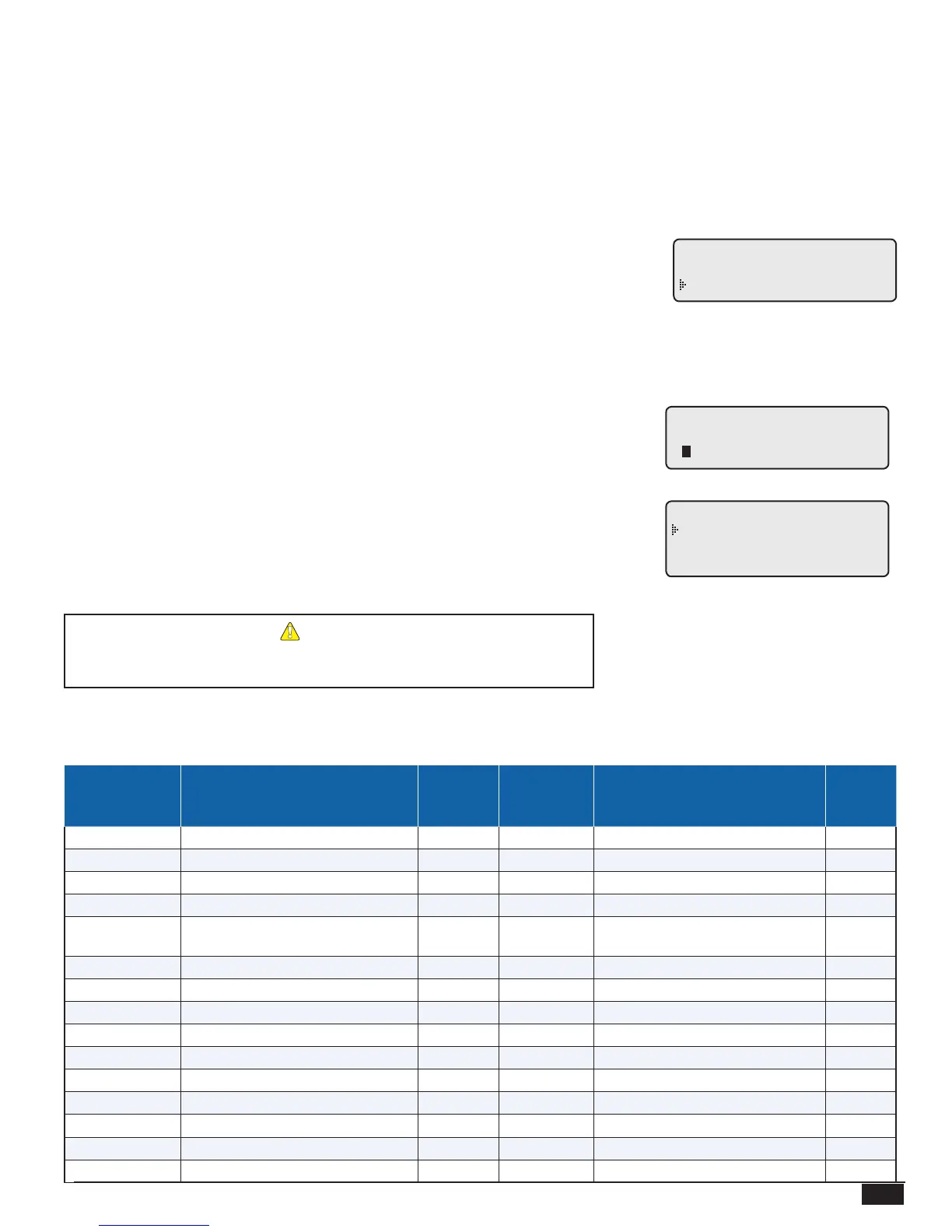
--NETWORK SETTINGS--
MAC Address 1
Baud 9600
MODBUS COMMUNICATION OPTIONS
SELECT: MENU/<Settings>/<More Settings>/<Remote Interface>/Network Setting
• Before connecting the Platinum control to the MODBUS network, the user must set the following parameters according to the
MODBUS Network Administrator's instructions.
MAC ADDRESS
Options: From 1 to 247 Default: 1
• This is a unique ID within the MODBUS network. It must be provided by the MODBUS
Network Administrator.
---- MAC ADDRESS ---
1
[
]
MODBUS BAUD
Options: 9600, 19200, 38400 Default: 9600
• The Baud determines the speed of communication.
• Both the Platinum control and BMS must use the same Baud rate.
• The communication is xed to 8 Data Bits, No Parity, and 2 Stop Bits.
------ BAUD RATE -----
9600
19200
38400
ALERT
MODBUS capable Platinum controls will display --NETWORK PANEL--
on the 2nd row of the display when in screen saver mode.
MPC PLATINUM MODBUS VARIABLE LIST
MULT
1
(if not 1)
UOM
READ
ONLY
MPC
Platinum REG
/ VARIABLE#
1 – 3
DESCRIPTION
Model
RANGE / STATES / SPECIAL
VALUES
6 Character string
♦3
X
4 – 13 Serial Number 20 Character string
♦3
X
14 Firmware Version 100 X
15 Vari-Boost Adjustment 10 none 0.1 – 6.4
16 Boost Mode
0=Disabled, 1=Manual,
2=Vari, 3=Vari+ESD
17 Manual Boost Time Minutes 0 – 120
18,19 Bypass Time Minutes 0 – 2,147,483,647
♦4
X
20 Bypass Mode 0=AUTO, 1=ON
21 Cycle Length Minutes 10 – 240
22 Day Heat Adjustment 0 – 15 = A – P
23 Outdoor Day Cutoff °C, °F -6 – 38°C, 20 – 100°F
24 Day Light Saving 0=Enable, 1=Disable
25 Sensor Fault Mode 0=OutputOn, 1=OutputOff
26 System Differential °C, °F 2 – 42°C, 3 – 75°F
27 Sensor Mode 0=°F, 1=°C