HT# 059085-00 F
MPC
Platinum
PREV.
(DEL)
OUT
TEMP
AUX
INPUT 0
AUX
TEMP 0
AUX
TEMP 1
MENU FUNCTIONS
SELECT enters menus or accepts changes
ADJUST selects menu items or changes settings
BACK returns to previous menu
DAY selects next day
PREV./NEXT steps through output status
LINE
NEUTR AL
DAY
HELP NEXT
PRESS TO
SELECT
BACK
MON 12/28/04 10:43Am
ADJUST
A1
A2
A3
A4
A5
A6
A7
A8
A9
A10
A11
A12
AUX
TEMP 2
DO NOT APPLY ANY VOLTAGE
TO SENSOR TERMINALS
A13
A14
A15
A16
A17
A18
NETWORK
MSI CONNECTION
ON BACK
PROVE
SHUTDOWN
SYSTEM
TEMP
AUTO
BYPASS
ALL SENSORS MUST BE
GOLD SERIES SENSORS
INPUTS
ROUTE SENSOR AND AUXILIARY WIRES
THROUGH THIS KNOCKOUT ONLY
SYS
AUX
CLOCK
OPTION
1
OPTION
2
T
T
T
Cycle On
Cut= 55
o
F Day
OD= 31
o
F SYS= 148
o
F
OUTPUT
B
BURNER
MOTORIZED
VALVE
SYSTEM OPTION
1
OPTION
2
OPTION
3
AUX
CLOCK
T
T
C O R P O R A T I O N
R
2 3 4 5 6 7 8 9 11 12 13 14 15 16 17
OPTION
3
10 18
R W
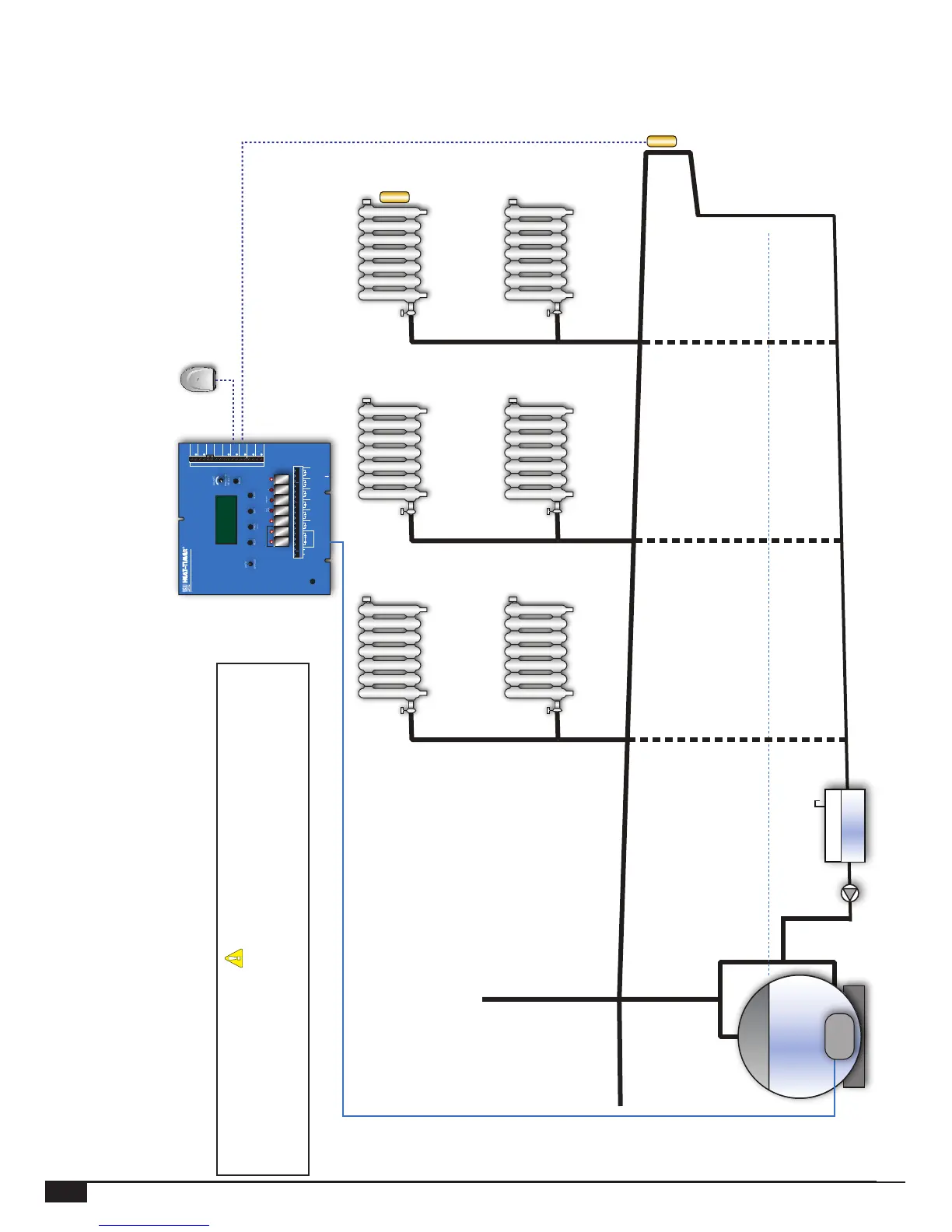
Outdoor
Sensor
MPC Platinum
Zone A
Boiler Water Line
Boiler
Zone B
Zone C
Condensate
Receiver
System Sensor
Installed on Dry
Return Above
Water Line
Optional Location:
System Sensor
At Furthest Radiator
Burner
MPC Platinum Settings:
ALERT
Since each installation is unique, Heat-Timer Corp. is not responsible for any
installation related to any electrical or piping diagram generated. The provided
illustrations are to demonstrate the control operating concept only.
46
MPC Platinum Installation and Operation Manual