E9Screen Software EPC9 Manual 38
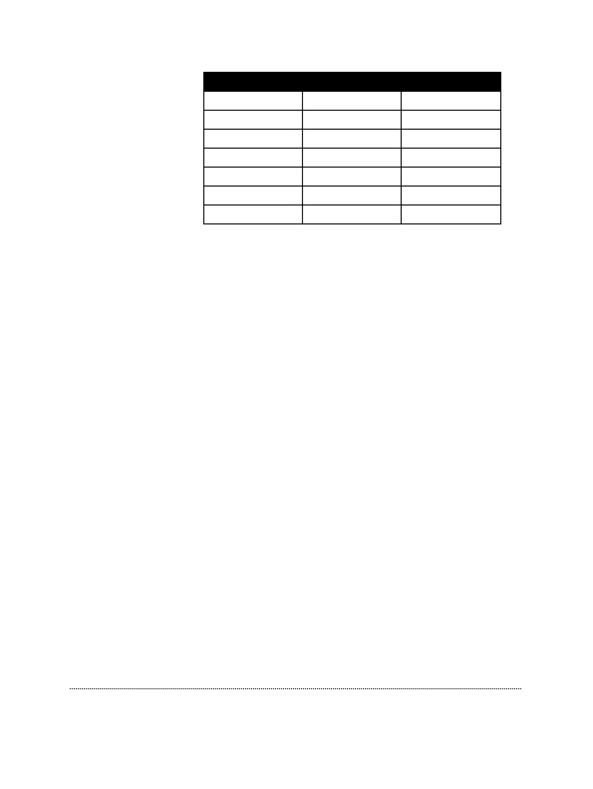
Low Medium High
Feedback Resistor 5 MΩ 500 MΩ 50 GΩ
Gain 0.005-0.002 0.5-20 50-2000
I
max
± 2 µA ± 20 nA ± 200 pA
Bandwidth 100 kHz 100 kHz 60 kHz
C-slow Ranges 30 • 100 • 1000 30 • 100 • 1000 30 • 100
Current Clamp no yes no
R
s
-compensation yes yes yes
The lowest range may be used for experiments (e.g., bilayers, loose-patch, or large
cells) in which large currents need to be delivered (up to about 2 µA). Capacitance
compensation of up to 1 nF is available and R
s
-compensation can be used for R
s
values down to 10 Ω in this range.
The medium and high gain ranges operate similarly to the EPC7. In the medium gain
range, the background noise is larger than in the high gain, but the full 100 kHz
bandwidth is available, and currents of up to about 20 nA can be recorded. This
range is used mainly for whole-cell recordings, and for this purpose the special
features of the 1000 pF transient cancellation range (see C-slow Ranges), series
resistance compensation, and the current-clamp modes are made available. On the
other hand, the high gain range is intended for single-channel recording. It has a
very low noise level, but this is obtained at the expense of a maximum current limit
of about 200 pA. The maximum available bandwidth is about 60 kHz, and the special
features mentioned above do not function in this range.
Slow capacitance cancellation ranges (30-100-1000 pF) can be set to any desired
value. However, in the high gain range (50 GΩ resistor) the 1000 pF range will not
operate. If the 1000 pF range is selected while the gain is higher than 20 mV/pA, the
gain will automatically be reduced to the highest possible setting (20 mV/pA).
Similarly, since the current-clamp mode is only possible in the intermediate gain
range (0.5-20 mV/pA), the gain will be reduced or increased appropriately when
selecting Current Clamp mode from an invalid gain range.
Clipping: A blinking box labeled “Clip” in the Gain title indicates saturation of
amplifiers in the current monitor circuitry. Like the Clipping LED on the EPC9 main
unit, this is a warning that excess artifacts or noise may occur due to the saturation of
amplifiers.
Note: This indicator may appear to be more sensitive than the LED on the EPC9. It is not;
it just latches the clipping status longer than the LED light.