E9Screen Software EPC9 Manual 40
Out Out Recording Modes), before the actual zeroing operation is performed. Auto-V
0
does this automatically and leaves V-membrane at that value.
Note: V
0
is not changed by the Reset function.
Track: This option implements a Search Mode (see Chapter 6. Operating Modes on
page 58), which is essentially a repetitive Auto-V
0
procedure at a holding potential of
0 mV. The rate at which Auto-V
0
is performed is determined by the Search Mode Delay
in the EPC9 menu.
LJ (Liquid Junction): LJ is a variable, to be set by the user, which allows to correct for
liquid junction potentials and other offsets. It works in conjunction with the V
0
operation. An online correction requires an Auto-V
0
operation to be performed before
seal formation and LJ to be set to an appropriate value. No correction is performed if
LJ = 0. See Chapter 7. Compensation Procedures on page 59 for more information on
how to determine LJ.
LJ can be adjusted within ± 200 mV by dragging the mouse or typing after a double-
click. Please note that LJ is not changed by the Reset function, and cannot be set by
macros. This restriction is imposed to avoid unintentional offset corrections.
LJ should be 0 mV when using identical pipette and bath solutions. It may be
changed to any desired value within ± 200 mV in case asymmetrical solutions are
used or the bath solution is changed during an experiment. For the standard liquid
junction potential correction, the polarity of the entered value should be such that it
represents the potential of the bath with respect to the pipette solution. For example,
if the pipette solution contains glutamate or aspartate (with chloride in the bath),
then the polarity of LJ should be positive (+10 mV). After an Auto-V
0
operation, V-
membrane will be changed to -10 mV (in Whole Cell and Out Out Recording Modes) or
+10 mV (for On Cell and In Out Recording Modes), which corresponds to the true
zero-current potential.
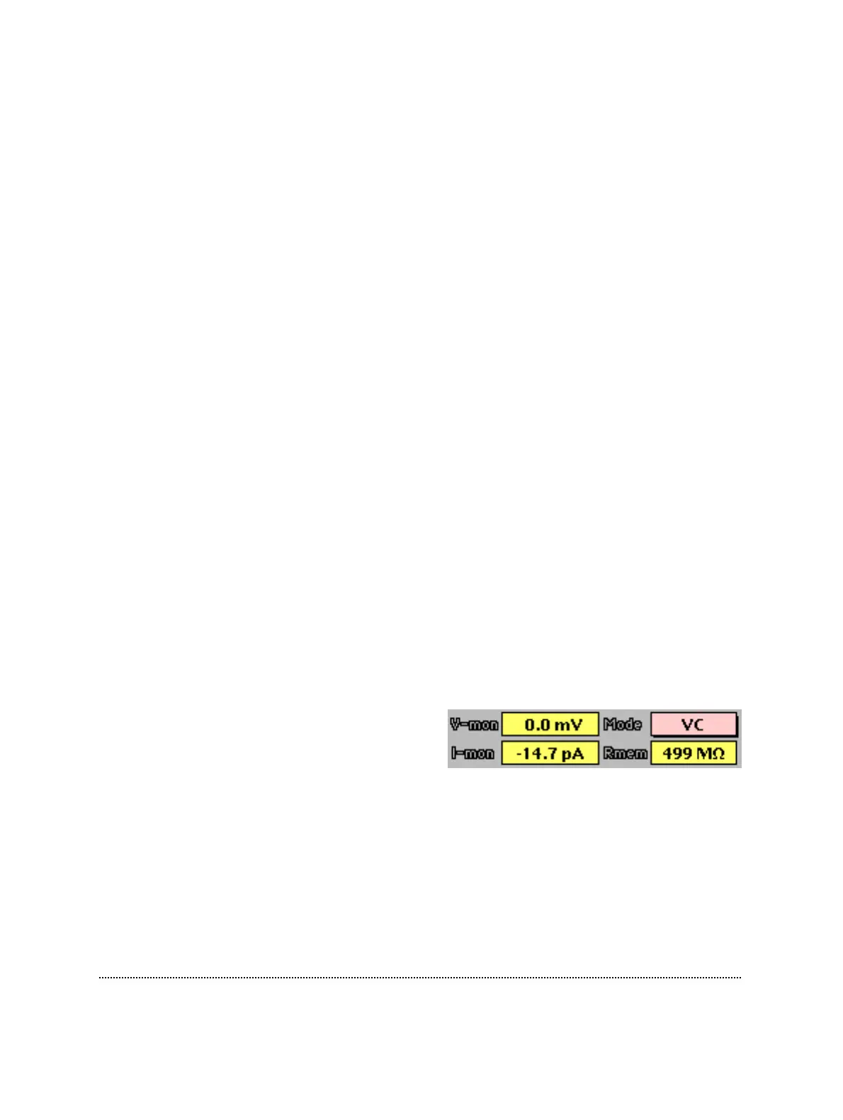
V-mon: Displays the actually-measured
pipette voltage after correcting for liquid-
junction potentials and offsets (provided the
zero-current potential has been set correctly). This may differ (temporarily) from the
holding voltage (e.g., during long stimulation pulses) as it indicates the average sum
of V-membrane and the scaled stimulus voltage.
I-mon: DC current monitor.
R-membrane: The Seal Resistance (R-membrane) is determined from the current
sampled during the baseline and the second half of the test pulse. R-membrane can be
encoded into a tone using the Sound feature.