QuickStart Guide REX 200/250 | Version 5 | 26.05.2021 6
3.2 Power source requirement
This device may only be operated with power supplies that meet the requirements of EN / IEC 60950-1
for power sources of limited power. Otherwise, the device must be operated in a housing that meets the
requirements of fire protection according to EN / IEC 60950-1.
3.3 Terminals and Interfaces
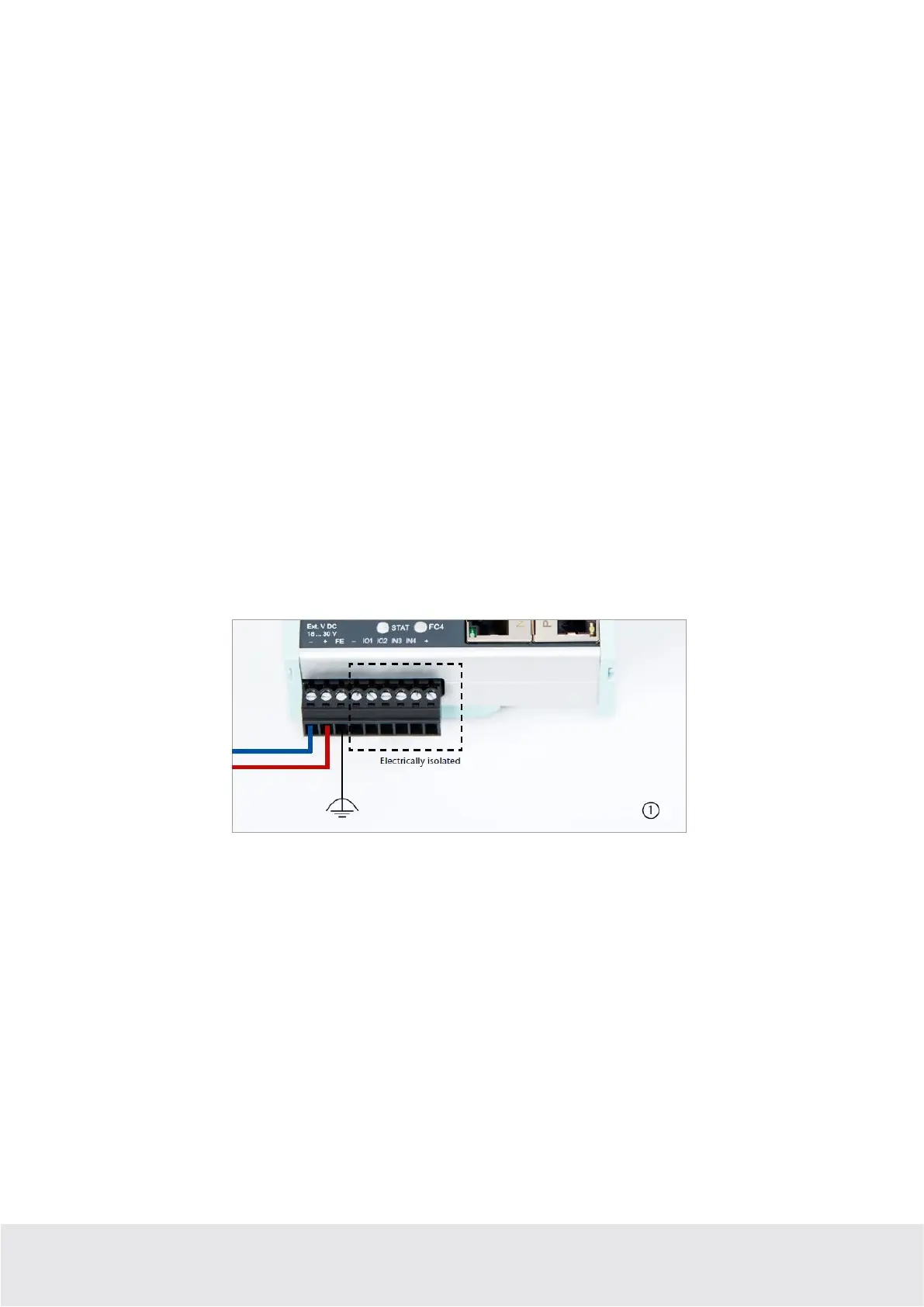
Rigid copper wires with a max. diameter of 1.5 mm² can be clamped onto the provided connector plug.
Network cables corresponding to at least category 5/5e (CAT-5) should be connected to the RJ-45 sockets.
3.4 Installation position/minimum clearances
The router was designed to be mounted on DIN rails (as per DIN EN 50 022) and intended for installation
in switch cabinets. Installation and mounting must take place in accordance with VDE 0100/IEC 364.
The router can be installed in any position.
It is recommended that minimum clearances to neighboring assemblies are observed during assembly. If
the distances 30 mm on the top and on bottom and 10 mm on each side are maintained, easy access to
the connections and contact options on the router is possible without having to remove other system
parts. In addition, there should always be enough space for the necessary cable routing.
3.5 2x IO1 & IO2 digital inputs/outputs and 2x IN3 & IN4
Due to the electrical isolation of the bi-directional input/output wiring, an additional supply voltage of
24 volts DC must be applied. The alarm inputs can be activated with potential-free switches, buttons or
relay contacts.
Depending on the configuration in the myREX24 V2 portal, one to four (or, in the case of multiplex
wiring, up to 99) different email/text message recipients can be alerted with individual message texts.
One input each can also be configured for establishing the connection to the myREX24 V2 portal or for a
REX system restart.