Indverter V2 Manual
Issue 03 Dated 11 November 2009 S/w Ver 12.4 HEXMOTO
Controls Pvt.Ltd
17
6 Prepare control and power cables as per the recommendations and ratings mentioned in “
Recommended cable type and terminations”. Grommets are provided to prevent entry of dust into
the module inner space.
7 Before connecting input power supply or motor to the drive module, ensure that motor shaft is free
to rotate and check for motor winding short circuit or Grounding faults.
8 Use proper lugs, ensure connectivity of the cables to the input, and output terminals on the drive
module.
9 Check proper operation of the control logic by referring to description of “ Control circuit interface”.
10 Switch ON input 415V mains voltage and measure 3-Phase input supply at INPUT terminals on the
drive module Power TBs using a multimeter in AC voltage mode.
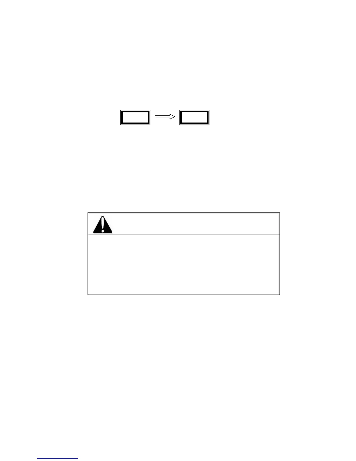
11 On start-up, drive module displays rated input voltage and module rating on LED display
indicating input rated supply voltage selection is for 3-Ph, 415V +10% -15%,50-60Hz input
Followed by module rating in kW
Example: r7.5 indicates 7.5kW Module, r22.0 indicates 22.0kW module
If input voltage is sufficiently high and if there are no faults, drive enters Ready To Run mode.
12 Refer to “Description of Parameters and programming” to configure drive for the application
requirement.
13 Close FOR/ REV TB input to start drive controller and run the motor. If start command as per Para
02 is from Display unit, press RUN/SET key to run the motor. Drive enters RUN mode and motor
starts rotating in FOR/REV direction.
14 Refer to “Maintenance and Troubleshooting” for any problem related to controller performance and
fault condition.
v415 r7.5
WARNING
• Before switching on the input power supply ensure that there is no cable
short circuit at the input/ output terminals
Shorting of cables between U, V, W terminals and OR shorting U, V, W
terminals to ground due to cable/ connection faults will result in IGBT
failure and damage to the drive controller.


 To Next Page