Indverter V2 Manual
Issue 03 Dated 11 November 2009 S/w Ver 12.4 HEXMOTO
Controls Pvt.Ltd
36
20 Aux Enable
When Para 20 is disabled, by setting as 0000, X3 terminal is used for multispeed functionality. If set to any
of the selection from 0001 to 0007 as described in “List of Parameters”, Auxiliary function is enabled.
Whenever X3 is activated (closed), reference for the drive is from auxiliary selection.
21 Restart after UV
Setting 0000 Trip and Latch
When the DC bus voltage goes below the Under voltage setting Para 20, the
Inverter will coast to stop. Under voltage trip will be indicated and latched. Upon
return to normalcy user has to RESET the fault.
0001 Stop and start with starting frequency
No Latching of fault
The Inverter will disable outputs as soon as the DC bus voltage reduces to the
under voltage setting and the motor stops. When the power returns or the DC
bus voltage rises above healthy level the inverter will start from start frequency if
the START Command is enabled
0002 Stop and start with Set Frequency after power returns
No Latching of fault
Operation is similar to setting 0001 except for drive re-starts with set frequency.
For safe operation Para 70 can be used to set Restart time limit.
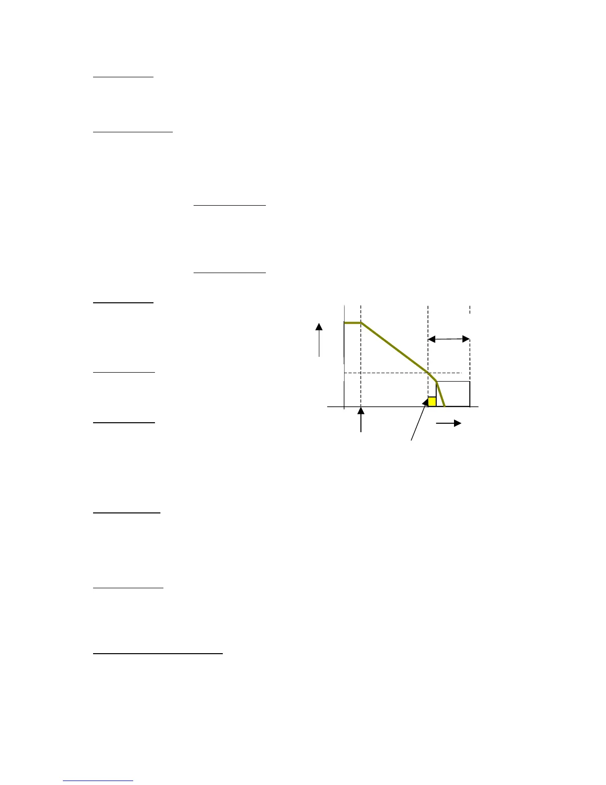
22 DC Inj Freq
When drive is decelerating to stop, Inverter will apply
Dc voltage as set by Para 24 to the stator on
reaching DC injection frequency and will be ON for
duration of DC injection time (Para 23).
23 DC Inj Time
Dc injection brake will be ON for the duration
programmed here.
24 DC Inj Volts
0 – 20% of the full output voltage
When installing drive system with DC injection
braking, use this parameter to adjust the DC voltage
that is to be applied to motor for safe operation.
DC Injection braking is not functional in Free
stop mode
25 Catch On Fly
This function enables the drive to find the speed of a free running motor. When this function is enabled, the
drive will start checking the motor speed from the maximum frequency. Due to the search time there may be
some finite delay between the Start command and the inverter output. The total delay can extend up to 10
seconds if the motor running speed is very low for Catch on Fly. The operation is dependent on Para 13
and Para 26
26 CFLY Current
This is the current at which drive catches with the free running motor. If the load is drawing maximum of
100% motor current during normal operation, then this parameter must be set to 100%. It is recommended
that the actual load current during steady state operation at full speed be measured and accordingly the
current in percentage is set here for better Catch On Fly performance.
27- 28 Acc time-1 -- Dec time-1
Acceleration and deceleration times set here are selected by the drive based on Para 68 or Para 03 . Refer
to description of these parameters.
Speed
Time
0
Para 22
Stop
Para 23
Time
No Pulse
200mS