Indverter V2 Manual
Issue 03 Dated 11 November 2009 S/w Ver 12.4 HEXMOTO
Controls Pvt.Ltd
34
07 Starting Frequency
In some cases the motor may not be able to develop the required Starting Torque. In these cases the
Starting Frequency will be increased. If the set frequency is less than Start Freq, drive cannot be started.
When command goes above start freq, motor starts running instantly at Start freq. Start frequency is
functional only during initial start, after which drive can be made to run at any frequency above 1.0Hz (
Minimum frequency).
08 Acc time
This is the time in seconds for the Inverter to reach Maximum frequency in Para 04 from Zero frequency
when start command is given. The setting resolution is 1Sec and can be programmed for a maximum value
of 9999 seconds
09 Dec time
This is the time in seconds for the Inverter to reach Zero frequency from Maximum frequency in Para 04
when STOP is activated. The setting resolution is 1Sec and can be programmed for a maximum value of
9999 seconds. Setting this value to 0000 will enable the drive to stop in 0.5 Seconds.
10 Torque boost
Different motors will have different stator IR drops. This causes drastic torque reduction in some situations
at low speed. To overcome this effect, stator voltage is increased at lower speeds and eventually it follows
the V/F curve based on the Boost Frequency selection Para 11
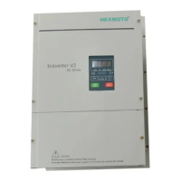
11 Torque boost cut-off frequency
Sets the frequency after which the torque boost
component in Para 10 becomes zero.
Using this parameter, it is possible to select required
V/F patterns for the application
Example
If the torque boost is 10% at minimum frequency of 1
Hz, 10% of the rated voltage is applied to the motor.
As the frequency increases, the amount of boost
added is slowly decreased and catches up with the
V/F curve at 50% of the base frequency value (
25Hz).
12 RPM Multiplier
This value is used for displaying the motor rpm or line speed. When the LED display Para 01 is set as “
Motor RPM”, the seven segment LEDs will display the product of output frequency and RPM Multiplier.
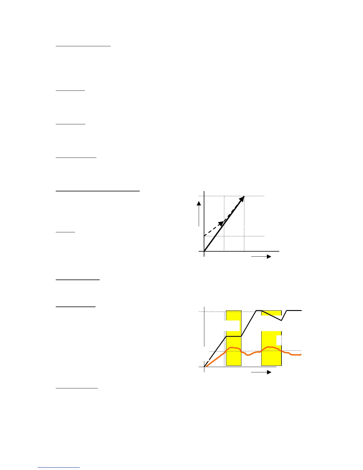
13 Current Limit
When the motor is accelerating, if the output current
reaches the level programmed here, the output
frequency will be steady. It will start accelerating
once the current is less than the value programmed.
This avoids the “Over current Trip During
Acceleration”
If the Inverter is running in steady state, crossing the
current limit will decrease the output frequency. This
avoids stalling because of sudden load variations.
14 Motor Current
Rated Current of the motor to be entered by the user. Current limit functionality, Catch-On-Fly and
Electronic Thermal overloads work based on this parameter. Maximum current entered here is limited by
the Inverter rating
V m
10% V m
 Loading...