Indverter V2 Manual
Issue 03 Dated 11 November 2009 S/w Ver 12.4 HEXMOTO
Controls Pvt.Ltd
32
01 LED Display
By default, drive is configured to display Set Frequency when in Ready To Run Mode and Running
frequency in Run mode. Setting Para 01 to various other options such as Motor RPM, Motor Current, and
DC bus voltage will enable user to view these values in the same LED display. But, when in Ready To Run
mode display either shows Hz or RPM based on the selection and other values can only be observed in
Run mode.
Example
Setting Para 01 to 0002,
02 Control Location
By default, drive is configured to be controlled using key and key on the display Unit.
User can modify this parameter to enable control of RUN/STOP commands from other inputs such as from
Terminal block or from Serial Communication (if enabled in Para 66 as slave).
Setting 0000 Press
button to start when in Ready To Run mode
Press STOP/RESET button to stop drive when in Run mode
Direction of rotation is determined by FOR/REV TB inputs.
Setting 0001 2-Wire operation
Start/Stop operation is from TB FOR/REV terminals
FOR ON, drive runs in Forward direction
REV ON, drive runs in Reverse direction
Setting 0002 3-Wire operation
Direction of rotation is determined by FOR/REV inputs, which are push buttons
If HOLD input is ON, Pressing forward pushbutton will enable drive to run in the
forward direction. Drive will continue to run in Forward direction as long as
HOLD is ON. If HOLD is released, drive will be stopped.
Setting 0003 Serial Communication for start/stop
Direction of rotation is controlled by serial communication data from a host
computer or Drive. Refer to “ Serial communication interface” for more details.
Setting 0004 Serial Communication for start/stop + FOR/REV
* Refer to “Operation of FOR, REV and HOLD inputs “ in Page 20
Ready to Run Mode
Blinking Display of Input
reference frequency
Hz LED Glows
50.00
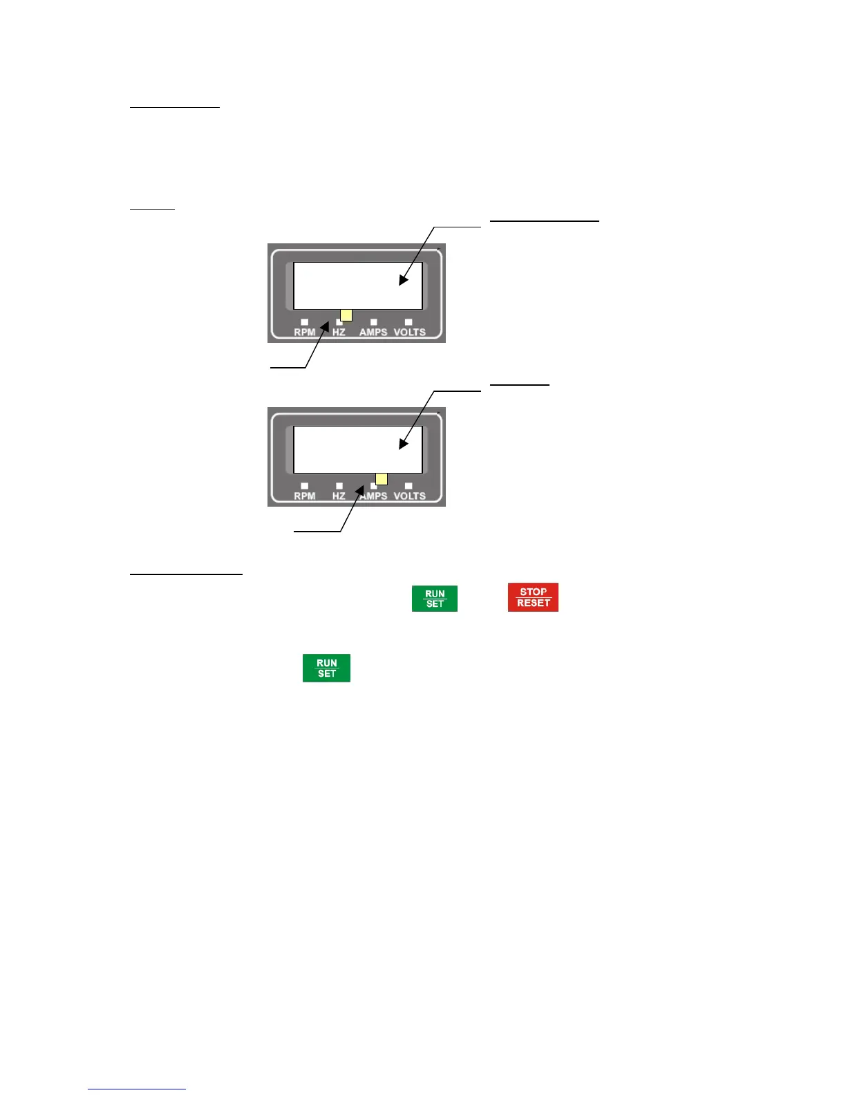
RUN Mode
Display shows Current
output from the drive
 Loading...