Indverter V2 Manual
Issue 03 Dated 11 November 2009 S/w Ver 12.4 HEXMOTO
Controls Pvt.Ltd
38
45 PWM Frequency
Certain combination of switching frequencies for particular motor load characteristics can create oscillations
in the motor performance due to resonance. User can vary the switching frequency to avoid such
oscillations. This is also called as “switching frequency” or “Carrier frequency” in Inverter drives terms.
Factory default setting is 4kHz. Reducing the PWM frequency creates more noise that is audible and less
loss in the inverter system. Increasing the PWM frequency will reduce audible noise but increases switching
losses in the inverter system.
46 S-Curve
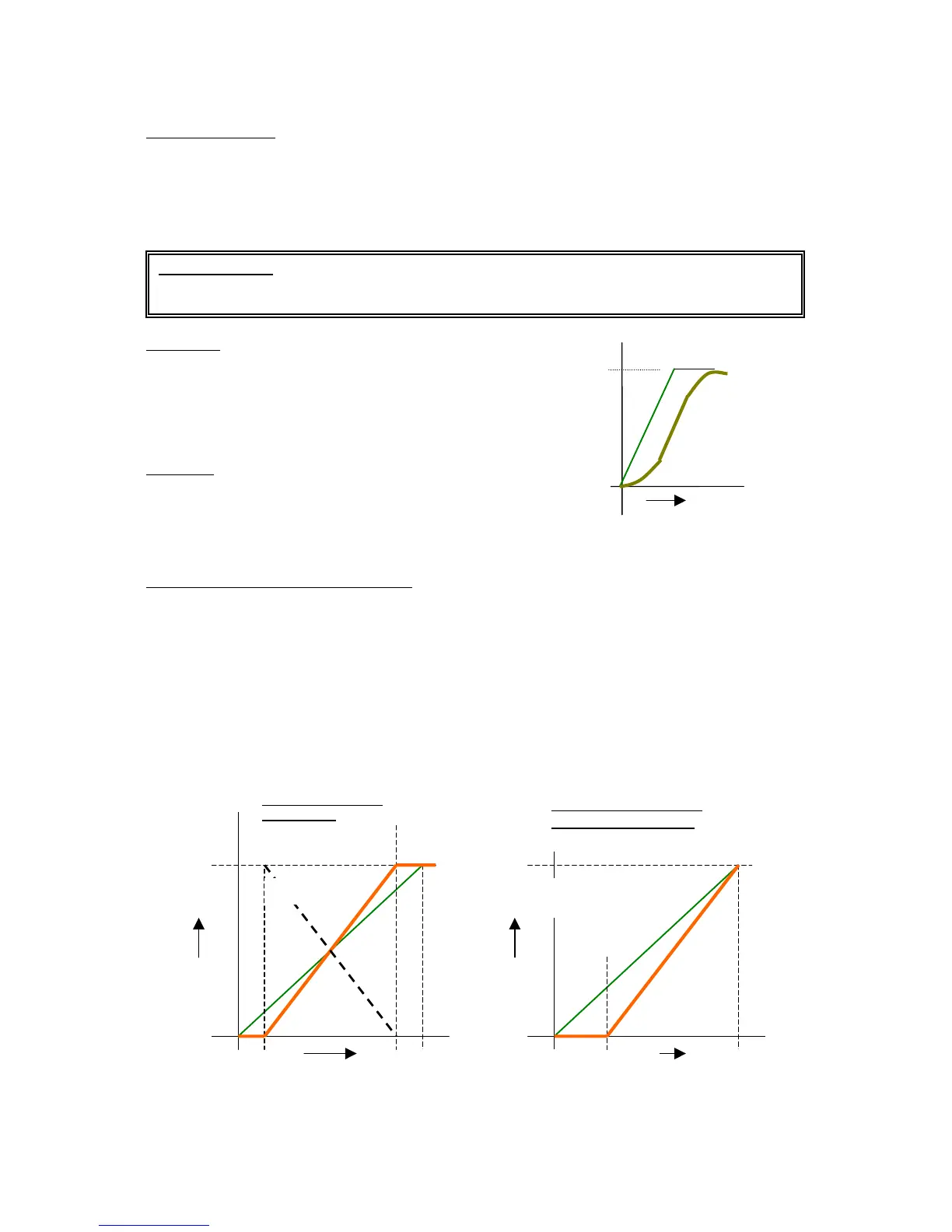
S-Curve acceleration/deceleration is used for
preventing shock at Start/stop. The curvature time is
dependent on time programmed in Para 47. Total
acceleration / deceleration time is extended due to S-
Curve by the time programmed in Para 47.
47 S-Time
Time in seconds for which the s-curve shapes the
edges. This is applicable if S-Curve Para 46 is
enabled
48 – 59 Analog input scaling parameters
Functionality of these parameters are based on Para 03. Refer to description of Para 03.
Functionality described below applies to analog reference inputs from VIN and AI+/AI- on control
TB.
Min
This is the percentage of analog input voltage/ current, which is considered as zero
reference for the drive controller. As shown in the figure below, Analog input is scaled for
new values.
Max
This is the percentage of analog input voltage/ current, which is considered as Maximum
reference for the drive controller.
Filt This determines the level of filtering or the filter crossover frequency for the analog input.
Neg Reference analog voltage/current input from Control TB VIN or AI+/AI- can be negated or
reversed by enabling this parameter.
* Important Note
The factory setting is optimal in most of the cases. Modification may be required in special cases
where the mechanical resonance is a problem.
Maximum Frequency
Reference input
0
Time
Maximum Frequency
10V


 To Next Page