Indverter V2 Manual
Issue 03 Dated 11 November 2009 S/w Ver 12.4 HEXMOTO
Controls Pvt.Ltd
35
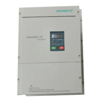
15 Electronic Thermal Overload
By default Thermal overload function is disabled.
Selection 0001
Separately Cooled Motor
When the motor is cooled from an external fan at
fixed speed, the cooling will be same irrespective of
the motor speed. Hence the Electronic Thermal
Overload Function will act like a standard bimetallic
Overload Relay. In the figure, 20Hz and above curve
is selected.
Selection 0002
Self-Cooled Motor
When the motor is cooled from shaft-mounted fan at
variable speed, the effect of cooling depends on
shaft speed. This is taken into account here and
Electronic Thermal Overload function works
accordingly. In the figure, 1 Hz to 20 Hz curves are
selected when the motor speed corresponds to less
than 20 Hz .
The example curve shown is for a motor with base
frequency of 50Hz
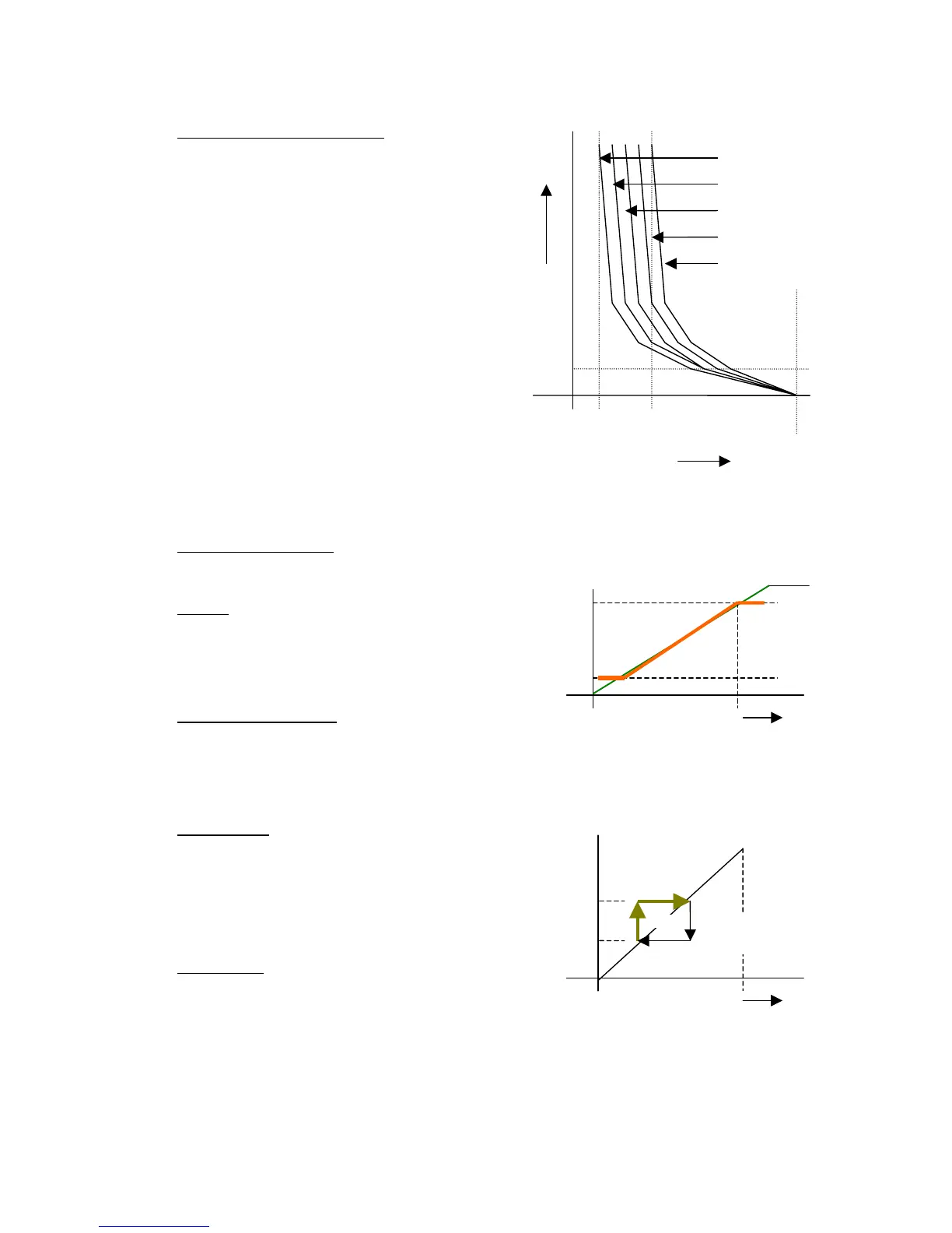
16 Frequency Low Limit
This function limits the running frequency
irrespective of the input reference.
Example
If the Frequency Limit Low is 10% and the Maximum
Frequency is 50Hz. the Inverter will run at 5Hz even
if the input reference is less than 5Hz.
This parameter should be always less than Para 17
17 Frequency High Limit
Increase in speed reference beyond this has no
effect on output frequency of the Inverter. The
parameter should be always more than Para 16
18 Jump Start
This is the starting of the Jump frequency. This
feature will make the Inverter to skip the frequency
from Jump-start to Jump End Para 19. In many
systems the resonance will occur when the motor
runs at particular speed. The vibration due to
resonance will be destructive and so it has to be
avoided.
19 Jump End
Refer to Para 18
The difference of Para 19 and 18 cannot be more
than 10% of the maximum frequency and Para 19
cannot be less that Para 18.
Motor Current
0
Time
60 sec
60% 100% 200%
1Hz to 5 Hz
5 Hz to 10 Hz
10 Hz to 15 Hz
15 Hz to 20Hz
20 Hz and
above
Maximum Frequency
Reference input
10V 0
Para 16
Para 17
Maximum Frequency
Reference input
10V 0
Para 18
Para 19
Deceleration
Path