Indverter V2 Manual
Issue 03 Dated 11 November 2009 S/w Ver 12.4 HEXMOTO
Controls Pvt.Ltd
18
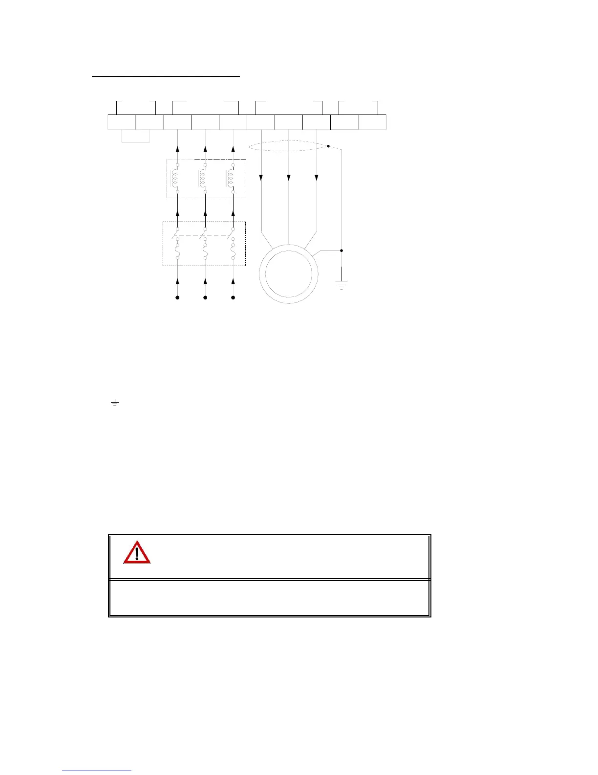
Description of Power Connection
NEG - VE R YB
U
BR
VWPOS
~
M
OUTPUT
3-PHASE MOTOR
INPUT
3-PHASE 50Hz/60Hz
415V +10% -15%
NEG, -VE : DC Reactor Terminals
R, Y, B : Input Power Terminals
U, V, W : Output Connection to Motor
POS, BR : Dynamic Braking Termilals
: Earthing Terminal
FUSE AND
MCCB
INPUT AC
REACTOR
X1
X2
Y1
Y2
Z1
Z2
OUTPUTDCR
INPUT DBR
• R, Y and B are input power terminals for 415V-15%, +10%, 3-Phase supply. The connection is not
phase sensitive. The connection can be done with any phase sequence.
• U, V, W are output terminals to the motor. The motor direction is dictated by the motor winding
pattern and phase sequence. To change the direction of rotation of the motor, change the
connection sequence to the motor or the direction (FOR/REV) command to the inverter. It is
recommended to use a 3 core armored cable or cable inside an earthed metallic conduit for motor
connection to reduce the electromagnetic emission and interference.
• POS, BR are connections for optional dynamic braking resistor
• If DC Reactor is not used, NEG, -VE terminals are shorted with a suitable cable rated for the
inverter rating. If DC reactor is used, disconnect this wiring and connect DC reactor here.
CAUTION
• When using the inverter for application where the direction of rotation is
critical, check the motor direction by running it with the load disconnected.


 To Next Page