Indverter V2 Manual
Issue 03 Dated 11 November 2009 S/w Ver 12.4 HEXMOTO
Controls Pvt.Ltd
44
related to input power to the drive system, Electro-dynamometer type watt meter in 2-
wattmeter configuration is preferred.
Trouble shooting
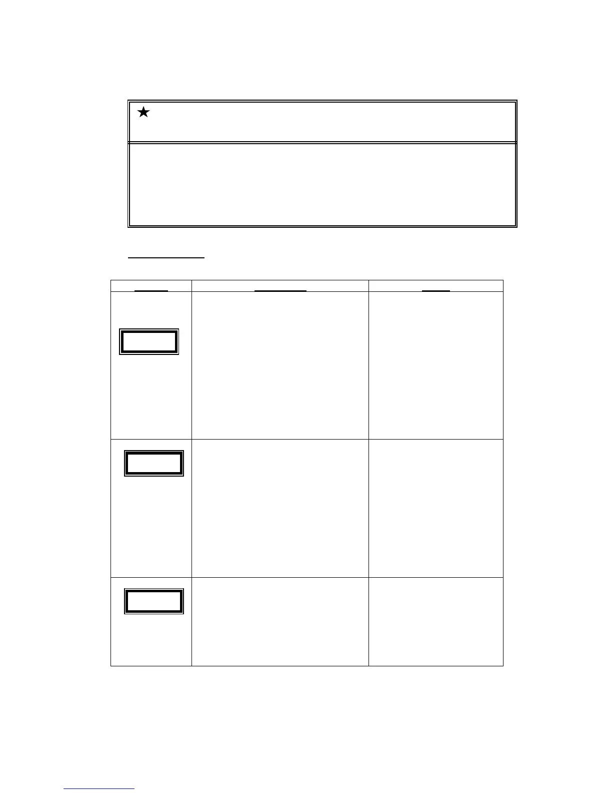
Display
Description Check
• Displayed when input 3-Phase
power supply voltage is less.
During start-up DC Bus voltage is
expected to be at least 400V DC.
Otherwise, system will wait for
input voltage to build-up before
entering Ready To Run Mode.
• After Power-up, if the drive input
voltage falls and goes below UV
setting in Para 20, display shows
dCLo. If Re-start parameter Para
21 is set as 0000, drive will trip for
UV
Measure input AC RMS voltage
at R, Y, and B terminals. Line –
Line AC voltage must be > 300V
and DC Bus measured between
Pos and Neg Terminals on
Power TB must be > 400V DC.
Check for proper 3-Phase
connection at the input terminals
• Displayed when DC Bus measured
by the controller is more than 760
V DC
If this fault appears before Run
command is given, verify the
input AC RMS voltage.
If fault appears when drive is
decelerating, Deceleration time
is very short for the load inertia.
Increase the deceleration time.
If optional brake unit is used,
check brake terminal
connections and Braking resistor
value
• Displayed when DC Bus measured
by the controller is less than UV
setting in Para 20. This is
applicable only in Run mode of
operation and when Para 21 is set
as 0000
Check for proper 3-Phase
connection at the input terminals.
If the fault persists even when
input voltage is OK, DC bus
capacitor/ balancing resistor or
the IGBT device may be faulty.
Important Notes on Measurement of voltages
Measurement of DC Voltage can be done between Power terminals POS and NEG. For 415 V 3-
Phase AC inputs, the DC voltage expected is around 550V Average
Measurement of Input AC voltages can be done at INPUT terminals between R-Y,Y-B and B-R.
The line-to-line voltages must be in the range of 415V +10% -15%.
dCLo
dCO
 Loading...