Indverter V2 Manual
Issue 03 Dated 11 November 2009 S/w Ver 12.4 HEXMOTO
Controls Pvt.Ltd
33
03 Main Speed Reference
Speed or Frequency reference is given to the drive controller using
Setting 0000 Display keypad UP/DOWN keys
Use UP/DOWN keys on display unit to increase or decrease speed reference
0001 Analog input from VIN terminal on TB
Potentiometer input using 10VA and GA from TB. Voltage range is 0-10V
0 – 10V corresponds to 0 to Maximum frequency in Para 04. Refer Para 52-55
0002 Analog Voltage input from AI+ AI- terminals on TB
Differential voltage input from PLC and other devices may be connected here.
If 10VA from Drive TB is used as voltage source, connect AI- to GA. Refer Para
48-51
0003 Analog Current input from AI+ AI- terminals on TB
If Jumper JP4 is inserted in Control card, AI+ and AI- terminals are used as
current inputs. 0-20mA or 4-20mA range can be set using Para 56 to 58
0004 Reference from Serial communication. If drive is configured as Slave in Para 66,
frequency/ speed reference is from Serial communication.
0005 Activating terminal X1 on TB will increase the speed with acceleration time in
Para 27. The digital input X2 will decrease the speed with a deceleration time in
Para 28.
If the drive is stopped or switched-OFF, the current frequency/ RPM is stored in
the drive memory. When the start command is issued, the drive will initially start
running at this stored frequency/ RPM.
0006 Function is similar to selection 0005. Except for if the drive is stopped or
switched-OFF, when the start command is issued again, the drive always starts
from minimum/ starting frequency. Also, X1 and X2 can be activated in Run
mode only
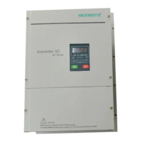
04 Maximum Frequency
This is the maximum frequency output possible from
the drive. All the other parameters, which control
frequency, are limited to this value. Maximum
reference input from any source such as analog
input or Digital keypad is scaled to Maximum
Frequency value.
05 Base Frequency
Base frequency is one at which the rated voltage is fed to the motor. The Inverter will maintain the linear
relation with the frequency (That is V/F ratio) and the rated output voltage will be applied to the motor at
Base frequency.
Further increase in the frequency will not have any effect on the output voltage and it remains constant.
Setting wrong base frequency value may result in damage to the drive and connected motor
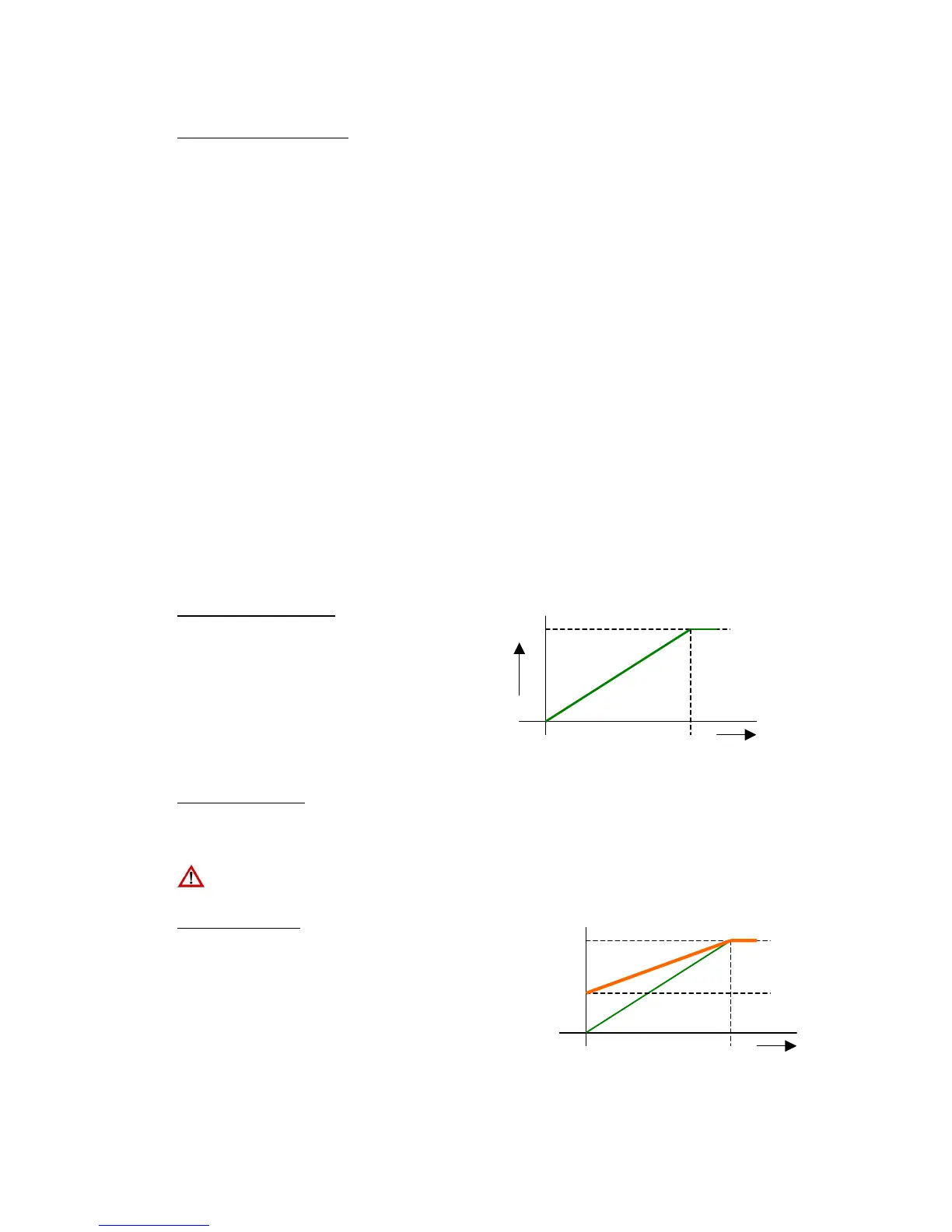
06 Frequency Bias
Bias frequency is the reference frequency when the
input reference signal is zero. This is used for
increasing the setting resolution. In practical it adds
an offset to the input analog signal and increases the
analog signal resolution. This is applicable to Analog
inputs only when Para 03 is setting is 0001,0002 or
0003.
Maximum Frequency
Reference input
10V 0
Ref input
10V 0
Bias 30%