DS-7700NI-SP/9000/9600 Series HDVR/NVR User’s Manual
14
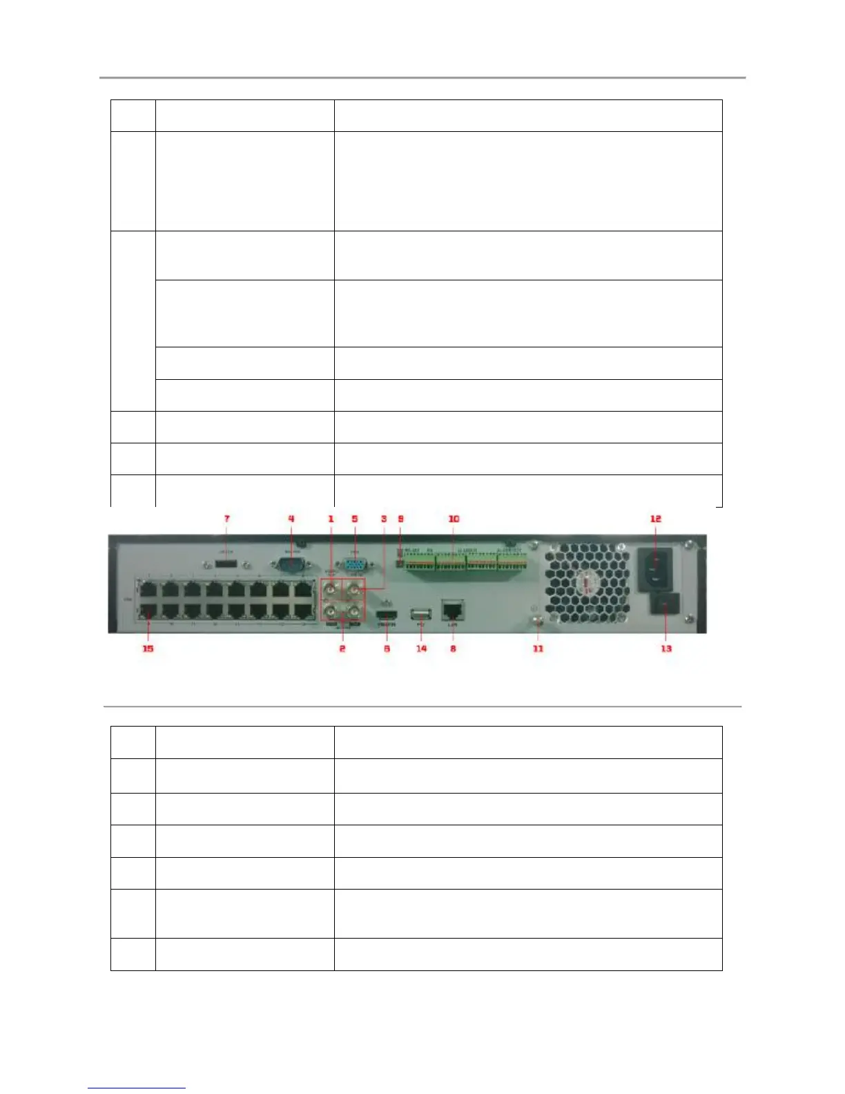
Connector for LAN (Local Area Network).
RS-485 termination switch.
Up position is not terminated.
Down position is terminated with 120Ω resistance.
Connector for RS-485 devices. T+ and T- pin connects to R+
and R- pin of PTZ receiver respectively.
D+, D- pin connects to Ta, Tb pin of controller. For
cascading devices, the first device’s D+, D- pin should be
connected with the D+, D- pin of the next device.
Connector for alarm input.
Connector for alarm output.
Ground (needs to be connected when device starts up).
AC 100V~240V power supply.
Switch for turning on/off the device.
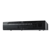
Figure 5 DS-7716NI-SP/16
BNC connector for video output.
RCA connector for CVBS and VGA audio output.
RCA connector for audio output.
Connector for RS-232 devices.
DB9 connector for VGA output. Display local video output
and menu.
HDMI video output connector.
 Loading...