18
Installation MACH104
Release
07
07/2014
The following table applies to all device variants:
If the manual adjustment is active on the “FAULT” signal contact, then the
detected error display is independent of the setting of the signal contact.
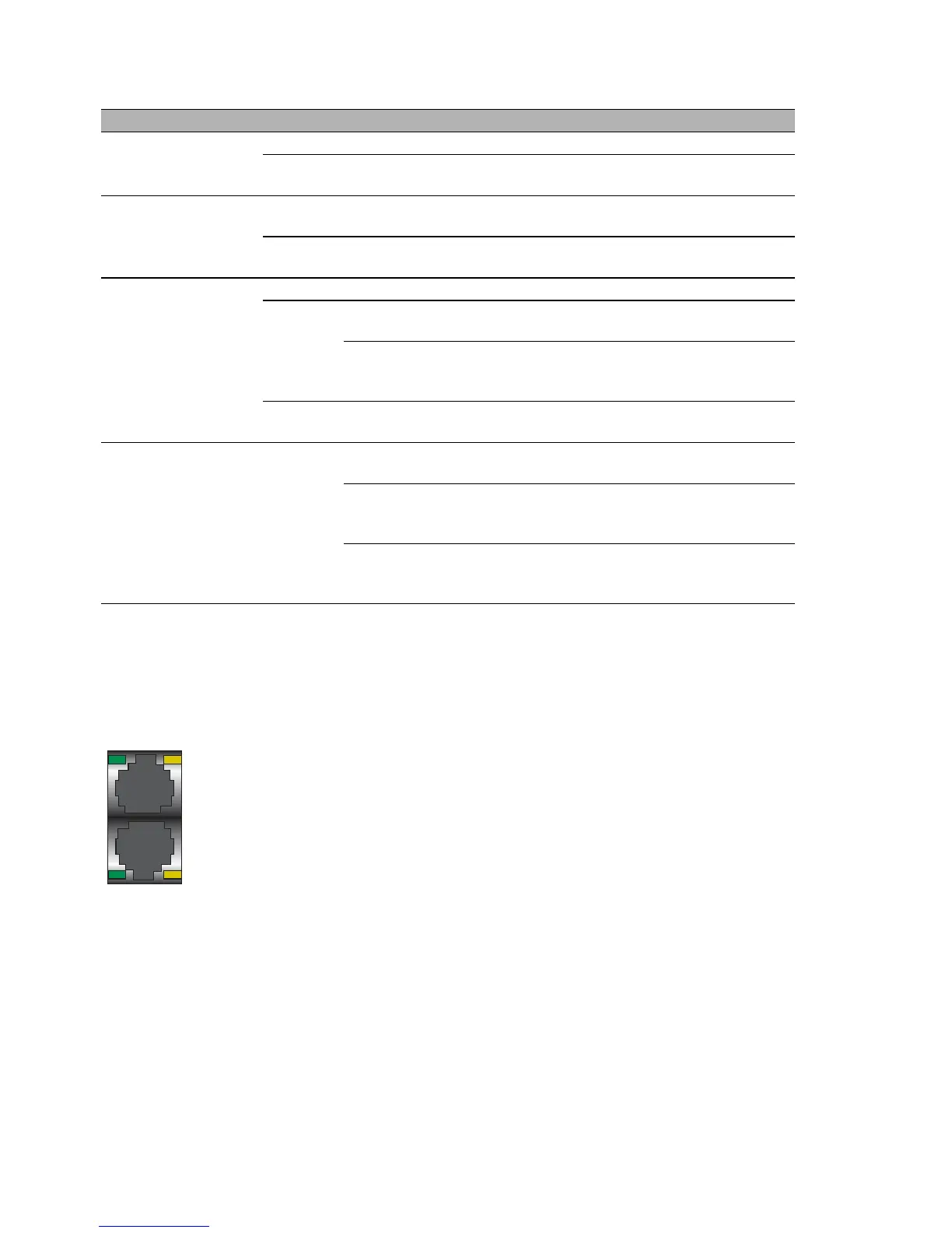
1.5.2 Port state
These LEDs display port-related information.
LED Display Color Activity Meaning
Sb Stand-by None Stand-by mode not enabled
Green Lights up Standby mode enabled
FAULT Signal
contact
None The signal contact is closed - it is not
reporting any detected errors.
Red Lights up The signal contact is open - it is reporting a
detected error.
RM Ring
Manager
None The RM function is deactivated.
Green Lights up The RM function is active.
The redundant port is disabled.
flashing The device detects an incorrect configura-
tion of the HIPER-Ring (e.g. the ring is not
connected to the ring port).
Yellow Lights up The RM function is active.
The redundant port is enabled.
RM
and
Sb
ACA
memory
operation
Flashing alter-
nately
Error in the memory operation
flash synchro-
nously – 2 x per
period
Save a configuration file from the ACA to the
device.
flash synchro-
nously – 1 x per
period
Saving a configuration file from the device to
the ACA.
 Loading...