EasyManua.ls Logo

Hitachi APCQ - Page 11

Hitachi APCQ
47 pages
Print Icon
To Next Page IconTo Next Page
To Previous Page IconTo Previous Page
Loading...
APCQ CAPACITOR BANKS
STATUS
Approved
SECURITY LEVEL
Public
DOCUMENT ID
9AKK107680A4136
RE V.
E
LANG.
en
PAGE
11/47
© 2022 Hitachi Energy. All rights reserved
.
3
1
7
2
4
8
10
6
5
9
9
11
12
13
13
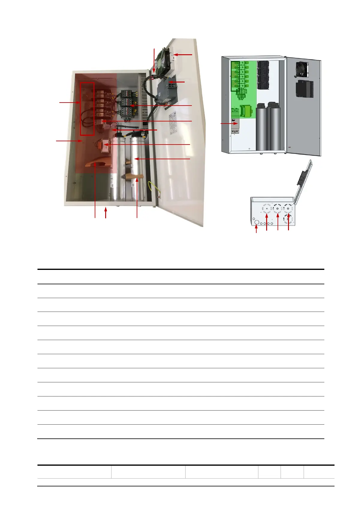
Figure 6: APCQ-L internal layout
Number
APCQ-M & APCQ-R Description
1
Fans (air outlet)
2
Auxiliary transformer (optional)
3
Auxiliary connections (current transducer)
4
Power Factor Controller (RVC by default or RVT as an option)
5
UA contactors
6
Air inlet
7
Main busbar (3
-Phase) for bottom (by default) or top cable connections
8
QCap Power Module
9
Circuit breaker (optional)
10
HRC fuses
11
Protection plexiglasses covering copper bars

Table of Contents