APCQ CAPACITOR BANKS
© 2022 Hitachi Energy. All rights reserved
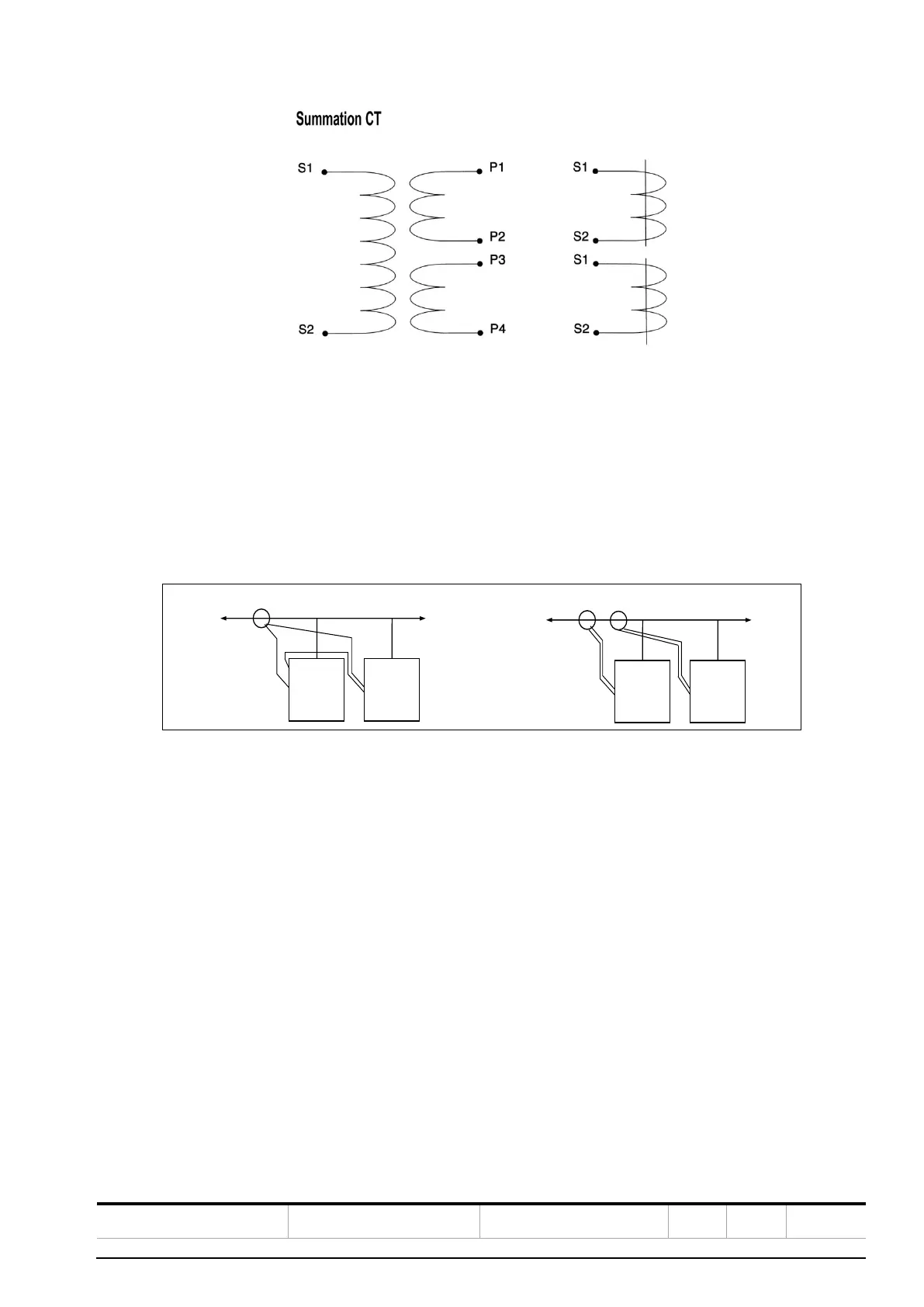
Figure 27: Summation CT
The first CT should be connected to P1 and P2 while the second CT should be connected to P3 and P4 on the sum-
mation CT. It is important that all CT’s monitor current in the same direction.
5.4.11. Connection of several banks in parallel
Several APCQ capacitor banks can be connected in parallel.
All APCQ capacitor banks are master units (i.e. fitted with a RVC or RVT controller) for better availability. If two units
or more are connected, they must be connected as per Figure 28.
Figure 28: Connection of several APCQ capacitor banks in parallel
The parameter “switching delay” of each RVC/RVT Controller must be set differently.
If the RVC/RVT controllers are set to normal mode, we recommend using a switching time delay difference of 1 sec.
(e.g. 40s, 41s, 42s …).
If the controllers are set to integral mode, we recommend using a switching time delay difference of 21 sec. (e.g.
120s, 141s, 162s …).
 Loading...