16
English
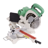
3. Using the vise assembly (Optional accessory)
(1) The vise asse mbly can be m ounted on either the
left side base or the right side base, and can be
moved back and forth according to the width of the
workpiece.
Insert support of vise assembly into the hole located
on either the left side base or the right side of the
base as sho wn in Fig. 20.
4. Cutting O peration
(1) As shown in Fig. 21 the width of the saw blade is the
width of the cut. Therefore, slide the w orkpiece to the
rig ht (vie w ed fro m th e o perator’s positio n) wh e n
length b is desired, or to the left w hen length a is
desired.
(2) O nce the sa w blade reaches maxim um speed, push
th e h a n dl e d o w n care fu l l y u ntil th e sa w bl a d e
approaches the w orkpiece.
(3) O nce the sa w blade contacts the w orkpiece, push the
handle down gradually to cut into the workpiece.
(4) After cutting the workpiece to the desired depth, turn
th e po w e r t o ol O FF an d l et t h e sa w bl a d e st o p
co m p le t el y be for e raisi n g th e ha n d le fro m th e
workpiece to return it to the full retract position.
CAUTION: * Increased pre ssure on the handle will not increa se the cutting spe ed.
On the contrary, too much pressure may result in overload of the motor and / or
decreased cutting efficiency.
* If the handle i s pressed down with excessive or l ateral force, the saw blade may
vibrate during the cutting operation and cause unwante d cutting marks on the
workpie ce, thus reducing the quality of the cut. Accordingly, press the handle down
gently and careful ly.
WARNING: * Confirm that t he trigger switch is turned OFF and t he power pl ug has been removed
from the rece ptacle whenever the tool is not in use.
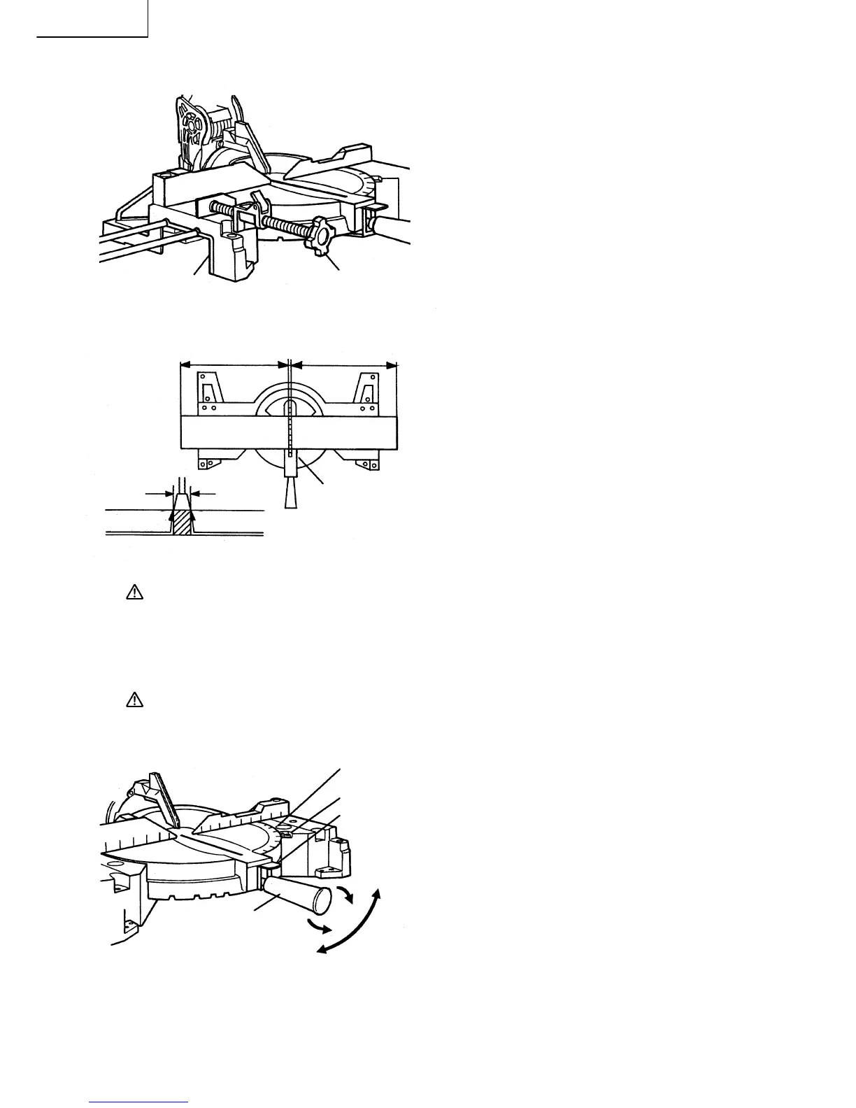
5. Miter cutting procedures
(1) Loosen the miter handle and push the spring plate.
(2) A djust the ta ble u ntil the indicator aligns with th e
desired setting on the miter angle scale as shown in
Fig. 22.
(3) Re-tighten the miter handle to secure the table in the
desired position.
NOTE: * Positive stops are provided at the right and left of the 0° center setting, at 15°, 22.5°, 31.6°, and
45° settings.
Check that the miter angle scale and the tip of the indicator are properly align ed.
* Operation of the power tool with the miter angle sc ale and indicator out of alignment, or with
the miter handle not properly tightened, will result in poor cutting precision.
Fig. 20
Vise
Assem blyBase
(Fro nt View)
Adjusting Line
ab
Marking
(pre-marked)
Marking
(pre-marked)
ab
a
b
Table Insert
Fig. 21
Workpiece
Fig. 22
Miter A ngle
Scale
Indicator
Spring
Plate
Tighten
Turn the
Table
Loosen
Miter Handle
 Loading...