17
English
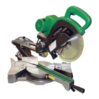
Fig. 23
6. Bevel cutting procedures
(1) Loosen the cla mp lever and bevel the sa w blade to the
left or to the right.
When tilting the motor head to the right, pull up the
locating bar as indicated in Fig. 23.
(2) A djust the b e v el angle to the desired setting while
w atching the bev el a n gle scale an d indicator, then
secure the cla m p lever.
WARNING: Whe n the workpiece is secured on the left or right side of the blade, the short cut-off
porti on will come to re st on the right or left side of the saw blade. Always turn the
power off and let the saw blade stop completely before raising the handle from the
workpiece.
If the handle is raised while the saw blade is still rotating, the cut-off piece may
become jammed against the sa w blade causing fragments to scatter about
dange rously.
7. Co m pound cutting procedures
For co mpound cutting, follow the instructions in paragraphs 5 and 6 above.
For maxim um dimensions for co mpound cutting, refer to “SPECIFIC ATIO NS ” table on page 9.
CAUTION: Always secure the workpiece with the right or left hand side f or compound cutting.
Never rotate the tabl e to the right for compound cutting (left bevel), because the
saw blade might then contact the clamp or vise that secures the workpiece, and
cause personal injury or damage.
Never rotate the tabl e to the lef t for compound cutting (r ight bevel), because th e
saw blade might then contact the clamp or vise that secures the workpiece, and
cause personal injury or damage.
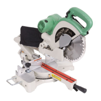
8. Crown molding cutting procedures
Fig. 24 shows two com m on cro wn molding types having angles of (θ) 38° and 45°.
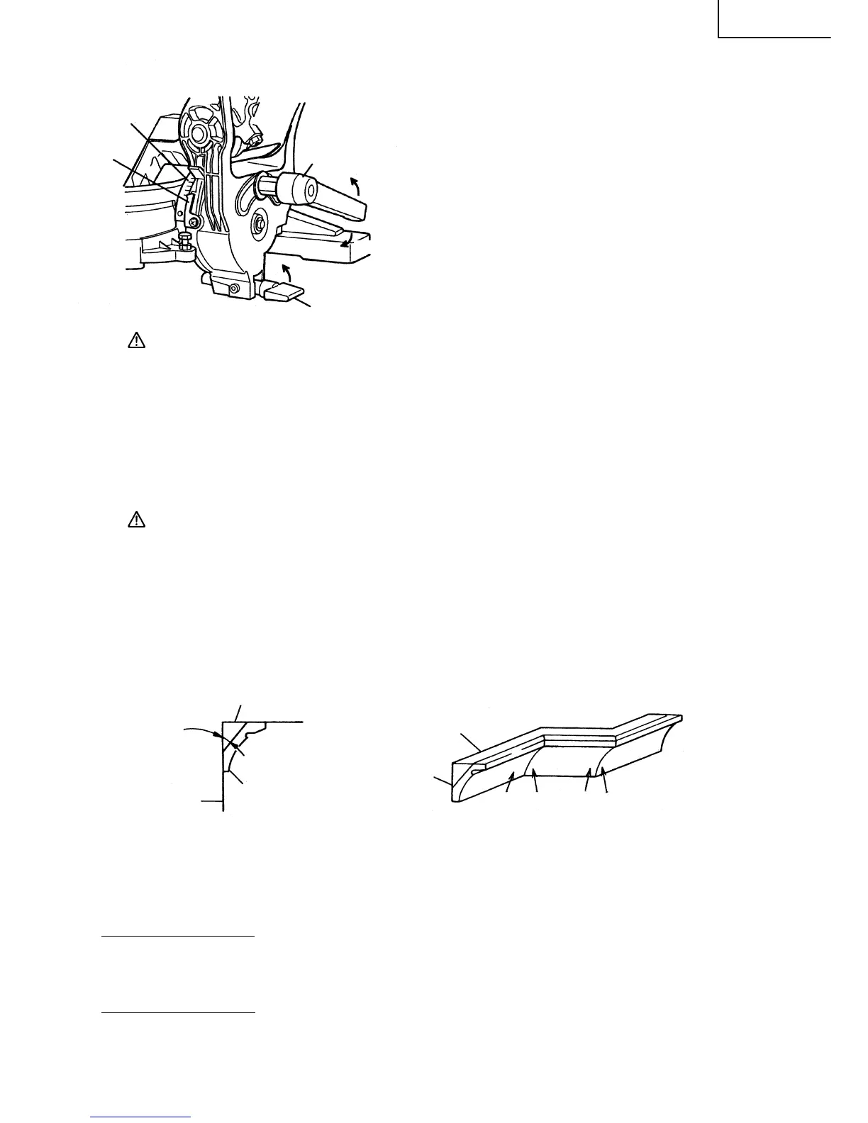
For the typical crown m olding fittings, see Fig. 25.
Fig. 24 Fig. 25
The table below shows the miter angle and the bevel angle settings that are ideal for the two cro wn
molding types.
NOTE: For convenience, positive stops are provided for the miter setting (left and right 31.6°) positions.
For miter cut setting
If the table has been set to either of the angles described, move the table adjusting miter handle a little
to the right and left to stabilize the position and to properly align the miter angle scale and the tip of the
indicator before the operation starts.
For bevel cut setting
Move handle on bevel section to the right and left and check that the position is stable and that the
bevel angle scale and the tip of the indicator are properly aligned. Then tighten the cla m p lever.
Loosen
Clam p
Lever
Pull
Up
Locating Bar
Indicator
Be vel A ngle
Scale
Tighten
Ceilin g
Wall
qw er
Wall
A upper surface
Ceilin g
B lo wer surface
θ°
 Loading...