18
English
Type of To process cro wn molding
at
To process crown m olding at
Crown M olding
positions 1 and 4 in Fig. 25.
positions 2 and 3 in Fig. 25.
Miter A ngle Bevel Angle Miter A ngle Bevel Angle
Setting Setting Setting Setting
45° Type right 35. 3° left 30° right 30° left 35. 3° left 30° right 30°
38° Type right 31. 6° left 33. 9° right 33. 9° left 31. 6° left 33. 9° right 33. 9°
( mark) ( mark) ( mark) ( mark)
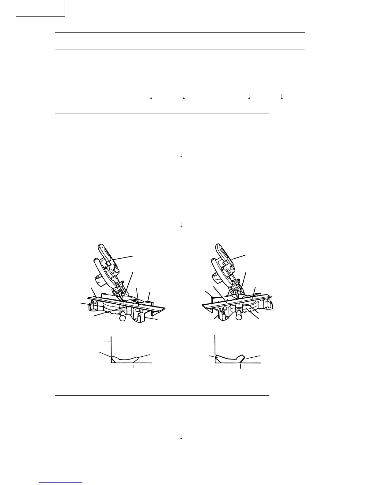
(1) Setting to cut cro wn m oldings at positions q and r in Fig. 25 (see Fig. 26):
q Turn the table to the right and set the Miter Angle as follo ws:
* For 45° type crow n moldings: 35. 3°
* For 38° type crow n moldings: 31. 6°
w Tilt the head to the left and set the Bevel A ngle as follows:
* For 45° type crow n moldings: 30°
* For 38° type crow n moldings: 33. 9° ( mark)
e Position the crown m olding so that the upper surface (A in Fig. 24) contacts the fence as indicated
in Fig. 27.
(2) Setting to cut cro wn m oldings at positions w and e in Fig. 25 (see Fig. 28):
q Turn the table to the left and set the Miter Angle as follo ws:
* For 45° type crow n moldings: 35. 3°
* For 38° type crow n moldings: 31. 6°
w Tilt the head to the left and set the Bevel A ngle as follows:
* For 45° type crow n moldings: 30°
* For 38° type crow n moldings: 33. 9° ( mark)
e Position the crown molding so that the lower surface (B in Fig. 24) contacts the fence as in Fig.
29.
Fig. 26 Fig. 28
Fig. 27 Fig. 29
(3) Setting to cut cro wn m oldings at positions q and r in Fig. 25 (see Fig. 30):
q Turn the table to the right and set the Miter Angle as follo ws:
* For 45° type crow n moldings: 35. 3°
* For 38° type crow n moldings: 31. 6°
w Tilt the head to the right and set the Bevel A ngle as follows:
* For 45° type crow n moldings: 30°
* For 38° type crow n moldings: 33. 9° ( mark)
e Position the crown m olding so that the upper surface (B in Fig. 24) contacts the fence as indicated
in Fig. 31.
q
Be vel
Angle Scale
r
Fe nce
Base
Miter Angle Scale
Table
Head
Miter Angle Scale
Be vel
Angle Scale
e
Base
Table
Head
Fe nce
w
Table o n Base
Fe nce
A
B
Fe nce
Table on Base
B
A
 Loading...