10.3.2 Wire size and Main switch protection
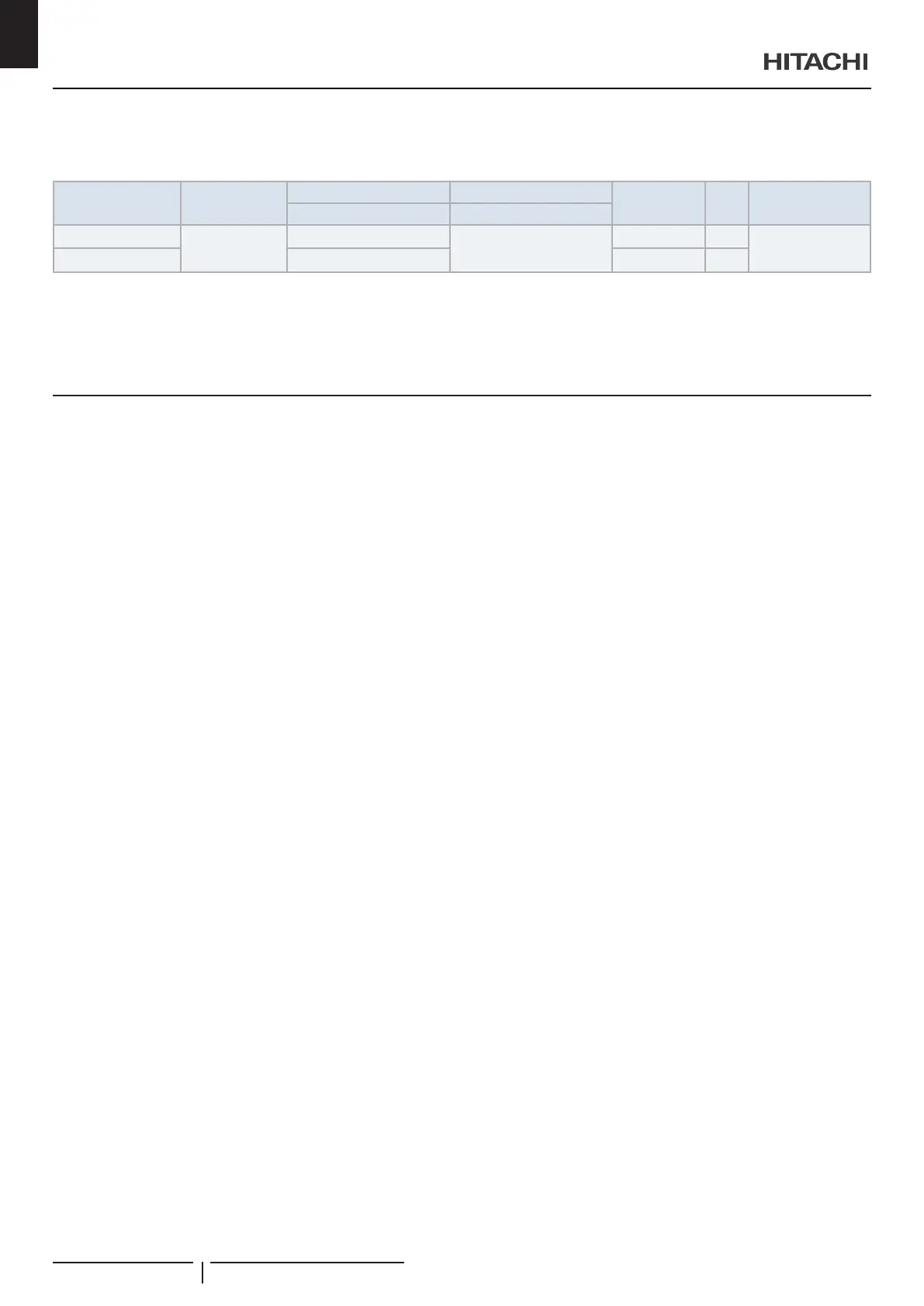
Recommended minimum sizes for eld provided wires and select the main switches according to the next table:
Model Power supply
Power source cable size Transmitting cable size
Max. current
(A)
CB
(A)
ELB
(nº poles/A/mA)
EN60 335-1 EN60 335-1
All Indoor Units
1~ 230V 50Hz
0.75 mm²
0.75 mm²
5.0 6
2/40/30
RAS-3HVRC2 4.0 mm
2
15.8 20
? NOTE
• ELB:EarthleakageBreaker;CB:Circuitbreaker
• Followlocalcodesandregulationswhenselectingeldwires,CircuitbreakersandEarthLeakagebreakers.
• Usethewireswhicharenotlighterthantheordinarypolychloroprenesheathedexiblecord(codedesignation60245IEC57).
11 COMMISSIONING
When installation is completed, perform test run according to the
following procedure, and hand over the system to the customer.
Perform test run regarding indoor units one by one in order, and
conrm that the electrical wiring and the refrigerant piping are
correctly connected.
! CAUTION
Donotoperatethesystemuntilallthecheckpointshavebeencleared:
• Checktoensurethattheelectricalresistanceismorethan1MΩ,by
measuring the resistance between ground and the terminal of the
electricalparts.Ifnot,donotoperatethesystemuntiltheelectrical
leakage is found and repaired. Do not impress the voltage on the
terminalsfortransmission1and2.
• Check to ensure that the stop valves of the outdoor unit are fully
opened,andthenstartthesystem.
• Checktoensurethattheswitchonthemainpowersourcehasbeen
ONformorethan12 hours,towarmthecompressoroilbytheoil
heater.
Payattentiontothefollowingitemswhilethesystemisrunning:
• Do not touch any of the parts by hand at the discharge gas side,
sincethecompressorchamberandthepipesatthedischargeside
areheatedhigherthan90°C.
• DONOTPUSHTHEBUTTONOFTHEMAGNETICSWITCH(ES),it
willcauseaseriousaccident.
• Donottouchanyelectricalcomponentsformorethanthreeminutes
afterturningOFFthemainswitch.
• Conrmthatthegaslinestopvalveandtheliquidlinestopvalveare
fullyopen.
• Conrmthattheleakageoftherefrigerantdoesnotexist.Theare
nutsaresometimesloosenedbyvibrationduringtransportation.
• Checkthattherefrigerantpipingandtheelectricalwiringconformto
thesamesystem.
• ConrmthattheDIPswitchsettingontheprintedcircuitboardofthe
indoorunitsandtheoutdoorunitsarecorrect.
• Checkwhetherornottheelectricalwiringoftheindoorunitsandthe
outdoor units are connected as shown in the chapter “10 Electric
wiring”.
! CAUTION
Conrmthateld-suppliedelectricalcomponents(mainswitchfuse,fuse-
freebreaker,earthleakagebreakers,wires,conduitconnectorsandwire
terminals)havebeenproperlyselectedaccordingtotheelectricaldata
givenintheTechnicalCatalogoftheunitandensurethatthecomponents
complywithnationalandlocalcodes.
? NOTE
For2 indoorunits system check the indoor unit outlet air temperature
at test run. If the temperature difference is large (aprox. 10 deg. or
more(cooling)20deg.ormore(heating)rechecktherefrigerantpiping,
installationmayhavesomeproblem.
COMMISSIONING
PMML0548 rev.0 - 04/2020 - A10648790A
14
EN





 To Next Page