CHAPTER
6
SCHEMATIC,
CIRCUIT
BOARD
AND
BLOCK
DIAGRAMS/
MICROPROCESSOR
PIN
FUNCTION
TABLES
Cautions
when
using
schematic
diagrams
Caution
for
safety
The
parts
marked
A
are
critical
for
safety.
Be
sure
to
use
the
specified
parts
to
ensure
safety
when
replacing
them.
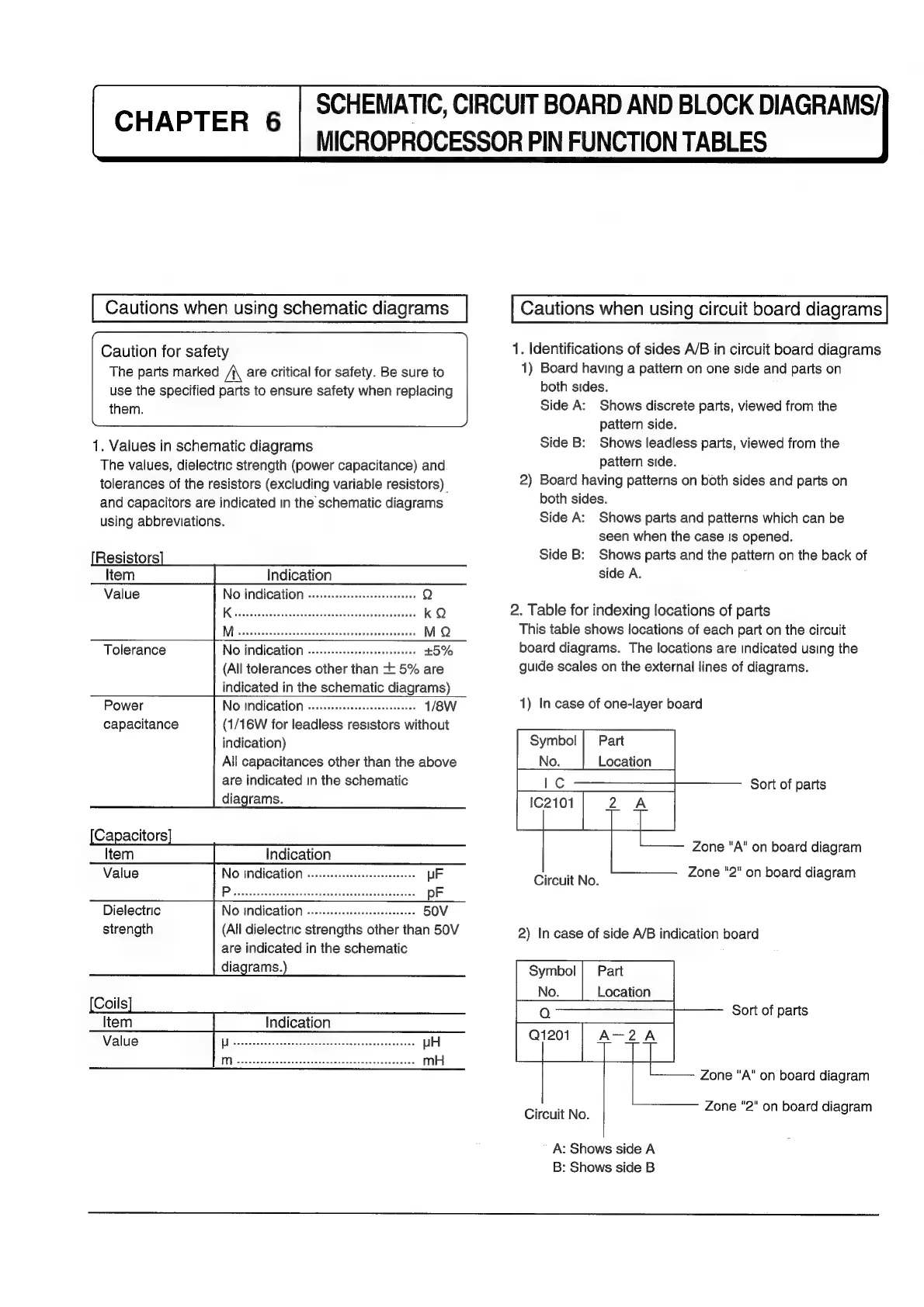
1.
Values
in
schematic
diagrams
The
values,
dielectric
strength
(power
capacitance)
and
tolerances
of
the
resistors
(excluding
variable
resistors)
and
capacitors
are
indicated
in
the
schematic
diagrams
using
abbreviations.
Indication
Value
NO
indication
...........:csssseeeeeeeeres
Q
KietetieccsnevetavccccclacccdsecdsvcSieeteseveis
kQ
MA
sisessesciuscectecdozectuwscguveuvvctavepenes
MQ
No
indication
..........cc:csseeeeeseeeees
(All
tolerances
other
than
+
5%
are
indicated
in
the
schematic
diagrams)
Tolerance
Power
NO
INdICATION
....0:ccccceeeeseceeeeseeees
1/8W
capacitance
(1/16W
for
leadless
resistors
without
indication)
All
capacitances
other
than
the
above
are
indicated
in
the
schematic
diagrams.
Indication
Value
No
indication
-.........cccscsseseseeseees
(All
dielectric
strengths
other
than
50V
are
indicated
in
the
schematic
diagrams.
Dielectric
strength
Indication
Cautions
when
using
circuit
board
diagrams
1.
Identifications
of
sides
A/B
in
circuit
board
diagrams
1)
Board
having
a
pattern
on
one
side
and
parts
on
both
sides.
Side
A:
Shows
discrete
parts,
viewed
from
the
pattern
side.
Side
B:
Shows
leadless
parts,
viewed
from
the
pattern
side.
2)
Board
having
patterns
on
both
sides
and
parts
on
both
sides.
Side
A:
Shows
parts
and
patterns
which
can
be
seen
when
the
case
is
opened.
Side
B:
Shows
parts
and
the
pattern
on
the
back
of
side
A.
2.
Table
for
indexing
locations
of
parts
This
table
shows
locations
of
each
part
on
the
circuit
board
diagrams.
The
locations
are
indicated
using
the
guide
scales
on
the
external
lines
of
diagrams.
1)
In
case
of
one-layer
board
Symbol
|
Part
No.
Location
LC
Circuit
No.
Sort
of
parts
Zone
"A"
on
board
diagram
Zone
"2"
on
board
diagram
2)
In
case
of
side
A/B
indication
board
Part
Location
Sort
of
parts
Zone
"A"
on
board
diagram
Circuit
No.
Zone
"2"
on
board
diagram
A:
Shows
side
A
B:
Shows
side
B