A99UE13-1304
8
2.2.The front and end joints of the linear actuator should be mounted onto two xed
positions on the main chassis. Locations of these xed positions should be chosen
according to the stroke length of the linear actuator (Users must be cautious that the
two-way movement of linear actuator must be smooth and within the stroke length
after installed onto the xed positions). Please ensure that no obstacle exists along
the travel path of the actuator.
2.3.After the xed positions have been selected, install the xtures onto these selected
positions of the main chassis. These xtures are used to x the front and end joints
of linear actuator to the chassis.
2.4.Assemble the front and end joints of the linear actuator onto the two xtures using
xture bolts. Please ensure that the xture bolts are able to rotate freely after this
step is completed. On the other hand, users should also make sure that the xture
bolts would not drop off either during operating or resting period.
2.5.The chassis of linear actuator should be xed in the horizontal direction if it is going
to be operated in this direction and likewise for vertical operation.
2.6.The operation of the linear actuator should be tested manually after the installation
is completed. Users should make sure that:
• The travel distance of the actuator is matching the requirement of the structural
design.
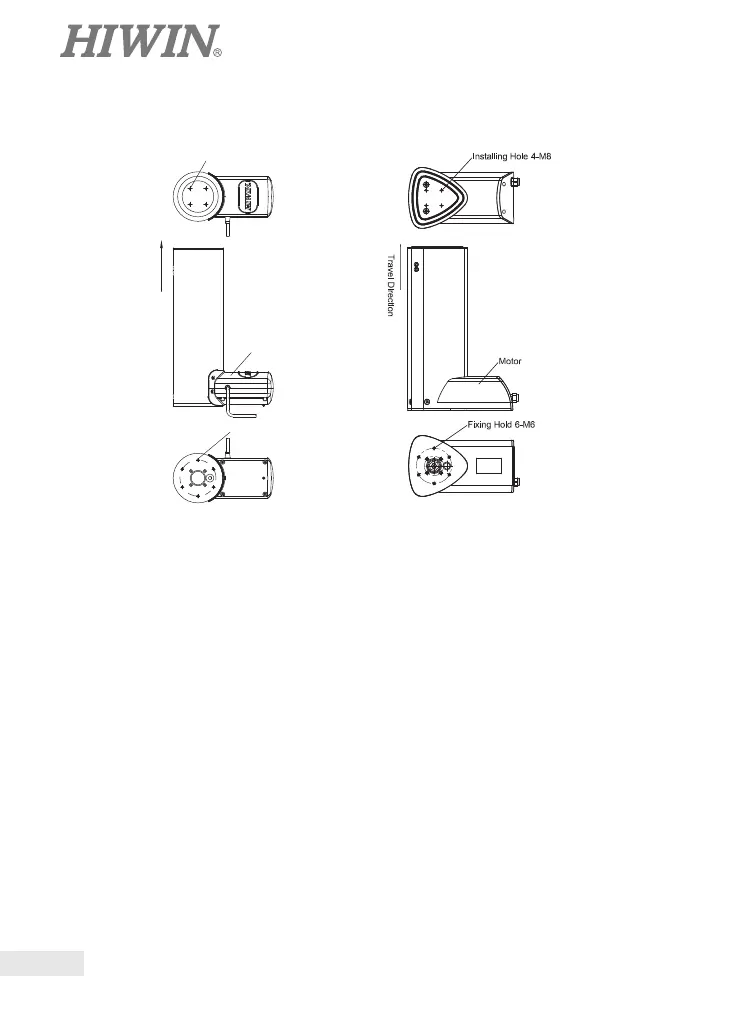
2.1.3 LAC1 Installation LAC3 Installation
Installing Hole 4 - M8
Travel Direction
Motor
Fixing Hold 6-M6
 Loading...