43
A99UE13-1304
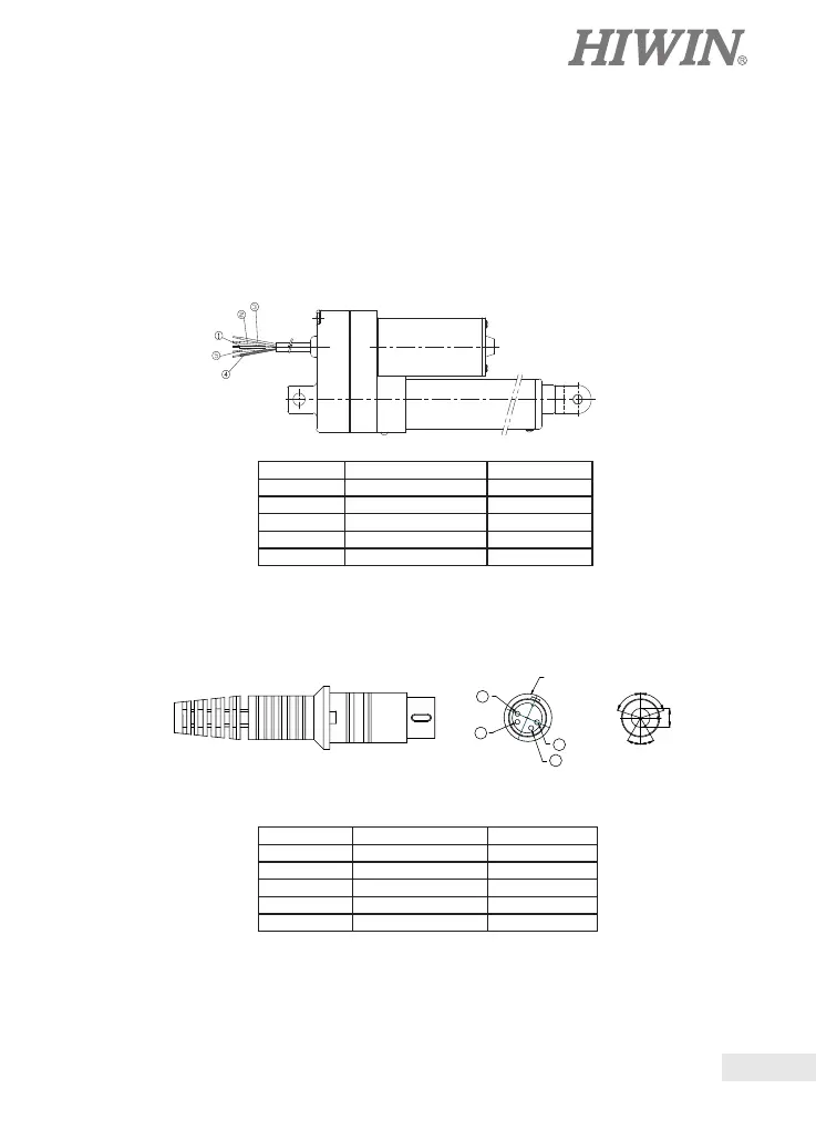
4. Positioning feedback device wiring
Positioning feedback device wiring can be classied as 5-core bare wire and 4-pin
connector described as follows:
1. LAS2、LAS3 Optical Sensor and Potentiometer Feedback
1.1 Bare Wire for Optical Sensor
1.2 4-pin Connector for Optical Sensor
4
3
1
2
SHELL
36¢X
0.7mm
36¢X
72¢X
72¢X
WIRING COLOR REMARK
1 BLUE (22AWG) GND
2 YELLOW (22AWG) OUTPUT
3 RED (22AWG) 24/12VDC
4 BLACK (20AWG) MOTOR(-)
5 WHITE (20AWG) MOTOR(+)
DIN Connector COLOR REMARK
1 YELLOW OUTPUT
2 BLACK MOTOR(+)
3 WHITE MOTOR(-)
4 RED 24/12VDC
SHELL BLUE GND
 Loading...