EasyManua.ls Logo

HOKUYO AUTOMATIC UST-05LN - Wire color and function

HOKUYO AUTOMATIC UST-05LN
53 pages
Print Icon
To Next Page IconTo Next Page
To Previous Page IconTo Previous Page
Loading...
Document No: C-41-02490-9
36
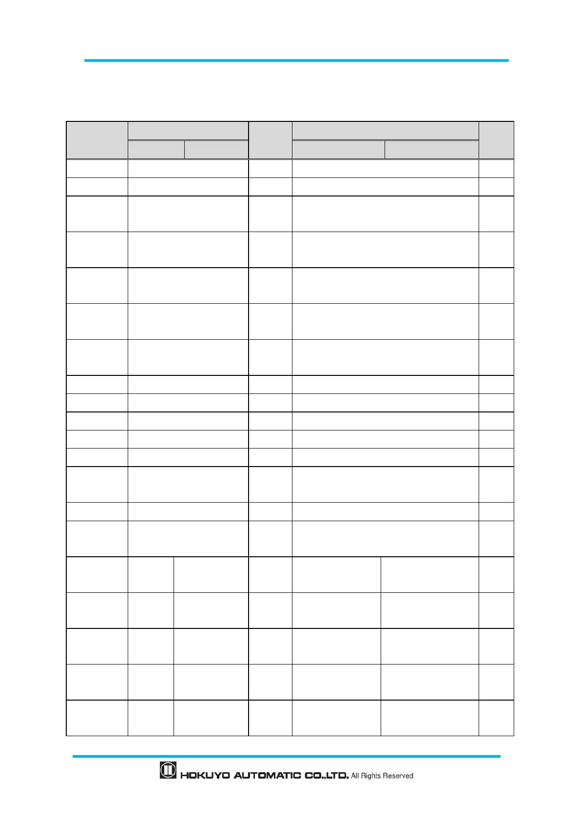
6.3 Wire color and function
Table 6-1 shows the color of each lead wire, signal name, function, etc.
Table 6-1 Wire color and function
Color
Signal
Function
Description
AWG
UST-05LN
UST-05LA
UST-05LN
UST-05LA
Brown
+VIN
Power
Power Supply: DC 12V or DC 24V
28
Blue
-VIN
Power
Power Supply : 0V
28
Black
Output 1
Output
When an object is detected in the output
region 1 it is turned OFF
28
White
Output 2
Output
When an object is detected in the output
region 2 it is turned OFF
28
White
(Blue)
Output 3
Output
When an object is detected in the output
region 3 it is turned OFF
28
Orange
Malfunction Output
Output
Turns OFF when malfunction output is
detected by self-diagnostic function.
28
Light green
Synchronous Output
Output
Synchronous output for Master/Slave
operation
28
Gray
COM Output -
Input
COM Output -
28
Red
COM Input +
Input
COM Input +
28
Green
Input 1
Input
Area switching Input 1
28
Yellow
Input 2
Input
Area switching Input 2
28
Purple
Input 3
Input
Area switching Input 3
28
White
(Black)
Input 4
Input
Area switching Input 4
28
White (Red)
Input 5
Input
Area switching Input 5
28
Light Blue
Synchronous Input
Input
Synchronous Input for Master/Slave
operation
28
Pink
NC
RS422 GND
Commu
nication
Non Connect
RS422 GND
28
Yellow
(Red)
NC
RS422 TXD+
Commu
nication
Non Connect
RS422 TXD+
28
Yellow
(Black)
NC
RS422 TXD-
Commu
nication
Non Connect
RS422 TXD-
28
Light Blue
(Red)
NC
RS422 RXD+
Commu
nication
Non Connect
RS422 RXD+
28
Light Blue
(Black)
NC
RS422 RXD-
Commu
nication
Non Connect
RS422 RXD-
28

Table of Contents

Related product manuals