Document No: C-41-02490-9
37
Note: Color names inside brackets indicate dual color cable.
Keep the input wires open or connected to input Com+ (red) if not in use.
Keep the output wires open or connected to output Com- (gray) if not in use.
Input/Output direction is defined from the sensor point of view (sensor as reference).
Attachment connector SHR-14V-S,SHR-06V-S(JST Mfg. Company) is for test purpose only.
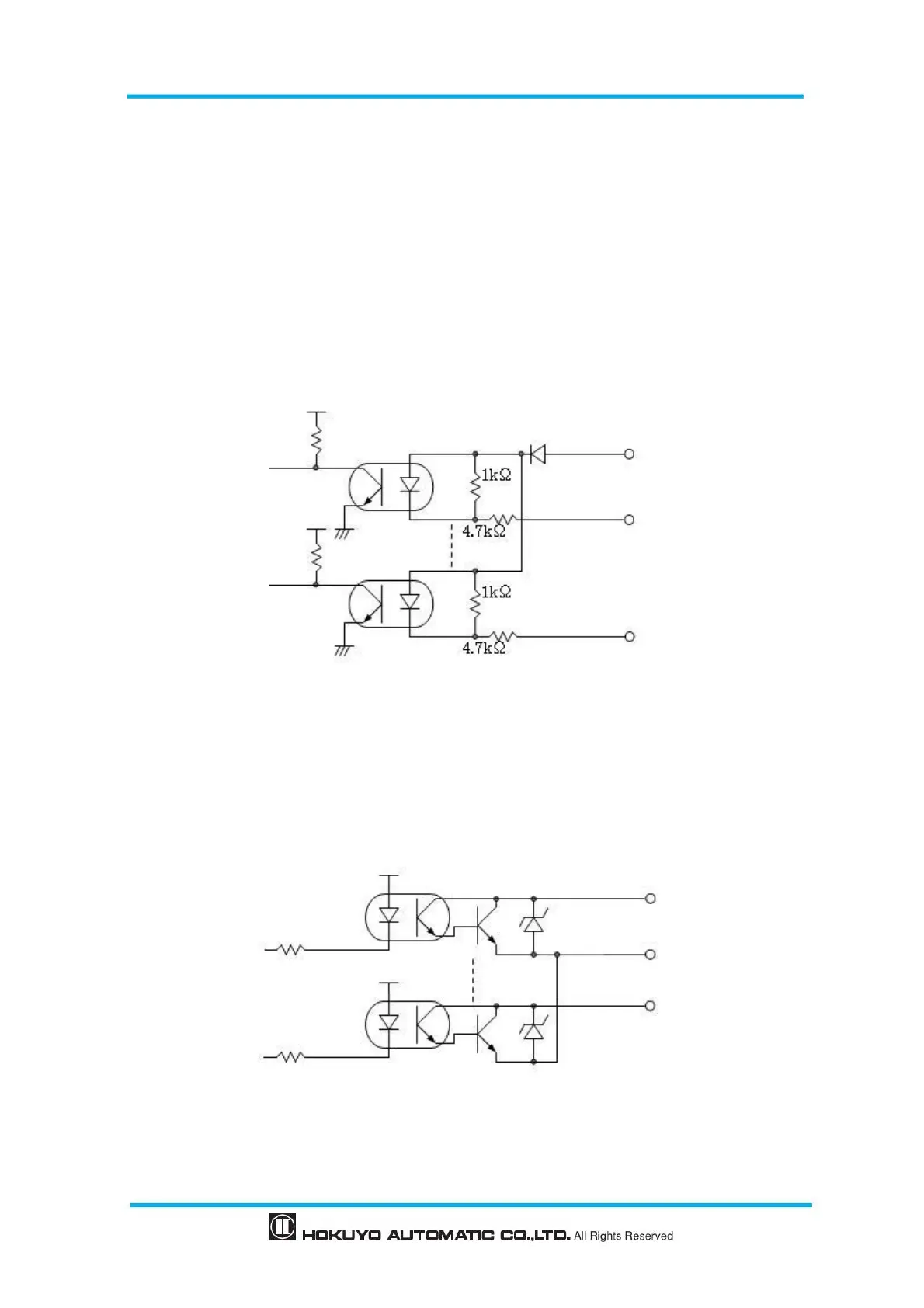
6.4 Input/Output circuit
6.4.1 Input circuit
Photo coupler input circuit (anode COM, Input ON current 4mA)
Figure 6-1 Input circuit
6.4.2 Output circuit
NPN open collector output circuit (maximum DC 30V, 50mA)
Figure 6-2 Output circuit